|
|
Post by captain chaos on Aug 6, 2013 19:26:51 GMT
You work fast m8.  Have you considered making up some bushings so that you can use the stock GS swingarm pivot bolt inside the Tiller swingarm? Yes, in fact I have another GSXR swingarm with a set of top hat bushes that would have fitted pretty much straight in. But.. : I'm using some of this project to experiment with a few things & replacing swingarm bushes is one of them. Even if I took the 'easier' route of using the 16mm GS spindle & top hat spacers I would still have the issue of the arm hitting the back of the engine casing. By installing new bushes I can also move them backwards to solve that. Additionally the larger diameter spindle of the TLR arm (25mm) gives me extra rigidity where I need it seeing as I have cut off the lower subframe tubes ;D Due to using a short usd front end I maybe have a bit too much downslope on the bottom frame tubes, I'm thinking I may also move the swingarm pivot up slightly to counter that. Have Tony Foales book & am trying to understand all the implications of doing this. The advantage so far are that it would lower the center of gravity & take a bit out of the steering head angle that was added by the short usd's. Anti squat will change as well but trying to understand that, all part of experimenting. Not going to piss about too much as needs to get built & bloody ridden  You will like the 'jig' I'm going to use for the job, roll on next weekend  |
|
|
|
Post by captain chaos on Aug 6, 2013 19:33:37 GMT
I finished my work on PeteG's ET  You know what that means  Be warned this post is a bit mad Need to move swingarm pivot backwards (arm hits engine) & replace the 16mm frame bushes with 25mm for the larger spindle. GJG had a neat way of removing the existing bushes on his Kat project (16mm spindle) he turned up some 16mm bushes with a pilot hole in them, welded them inside the stock bushes & then used a holesaw (with the pilot hole) to drill out the existing bushes. Measured the resultant hole & got new bushes made to suit. I thought some more & whilst a good method of removing I can do better with replacing & designed & had Super Larry make me a tool. This is a steel guide tube with one quadrant marked at 10's & also 45 deg, the other 2 items are alloy inserts with a central 16mm hole thru to match the existing GS swingarm spindle. 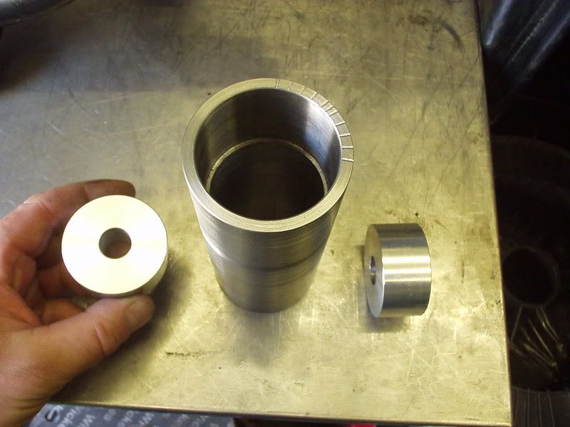 This is how it will work, 16mm inserts in tube, swingarm spindle in place & the guide tube set (approx) central in the frame. 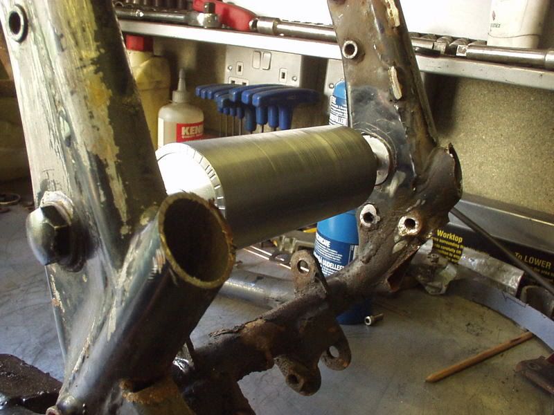 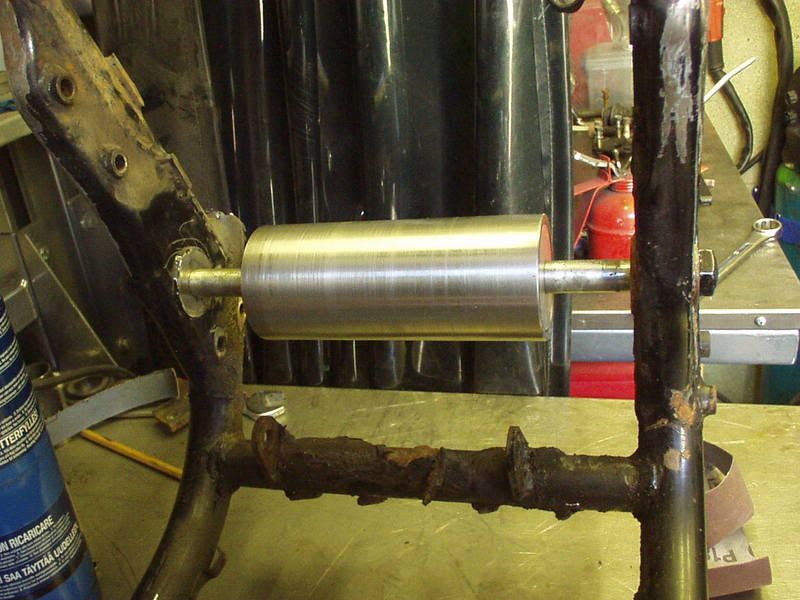 If I was doing this for real (& not testing) I would now use some lenghts of steel plate to tac weld the guide tube in place to some of the existing frame tubes. The idea is that the guide tube becomes the swingarm pivot reference whilst I replace the existing frame bushes. To do that I have copied GJG's idea & have some 16mm bushes with a pilot hole thru (but off center as far as poss because I'm moving my pivot point). Here you can see the bush in place & not very clear but has a scribe line on it so that I could set the pilot hole at any angle I wanted to assist in say moving the pivot back & up. 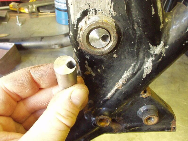 Here are some new alloy inserts for the guide tube with a 25mm hole thru for the TLR swingarm spindle size. I am intending to move the pivot point 6mm back & 6mm up, using right angle triangle thingy I then worked out how much off center the 25mm hole needed to be drilled in the insert. 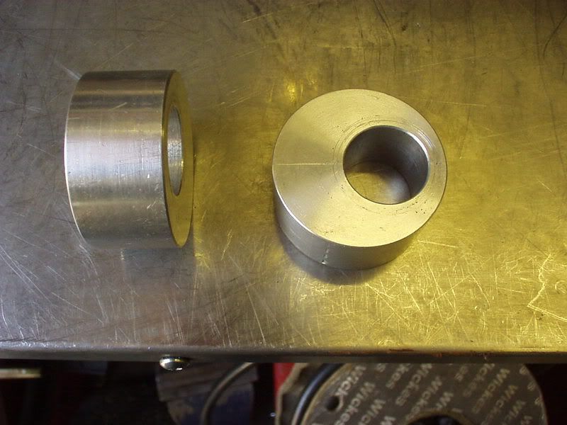 Assuming that I had drilled out the frame bushes & the guide tube was tac'd in place I could remove the 16mm alloy inserts, put in the 25mm ones & dial in an angle of 45 deg which would give me 6mm back & 6mm up. 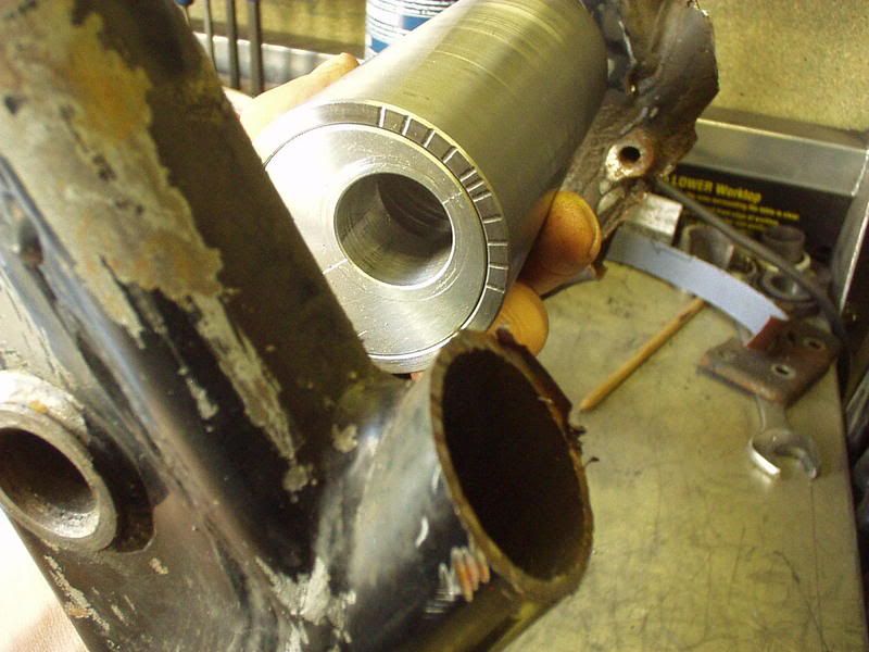 As more of a challenge the 25mm swingarm spindle I'm using for the TLR arm is from an SRAD 750 which is threaded both ends, which causes me a prob at the hex end as I don't need a thread. 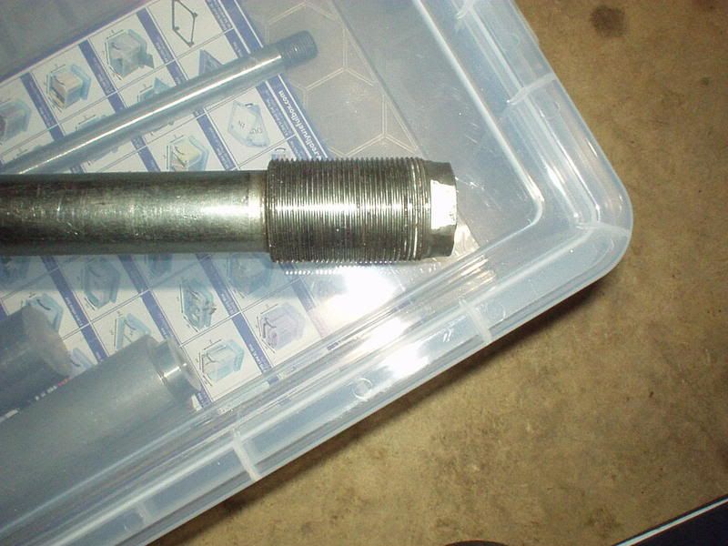 Got Super Larry to mod the spindle by loosing the threaded section & replacing with a hex. 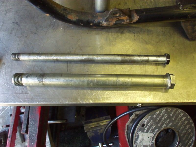 Which of course made the spindle too short. No problem I just had one of the new steel swingarm bushes threaded. If your still following this your doing well.. I wanted to be able to have something that represented the width of the new swingarm in place when I weld the new bushes into the frame. This next pics shows everything threaded onto the spindle but without the guide tube so you can see what's happening. On the spindle at either end are the new steel swingarm bushes, you can also see the 2 larger diameter alloy inserts & 3 smaller diameter tubes. The width of the 3 smaller tubes + the width of the alloy inserts = the width of the swingarm. 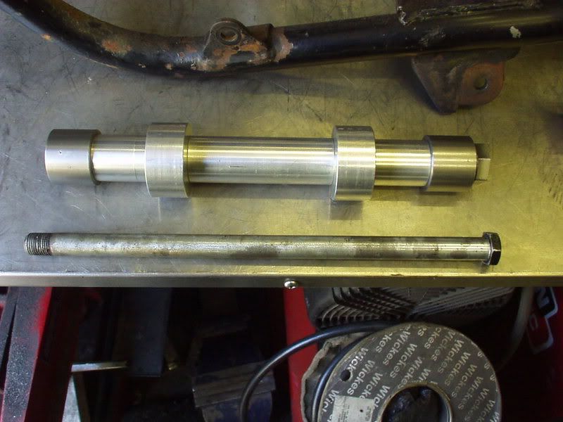 This is the same pic with the guide tube in place. 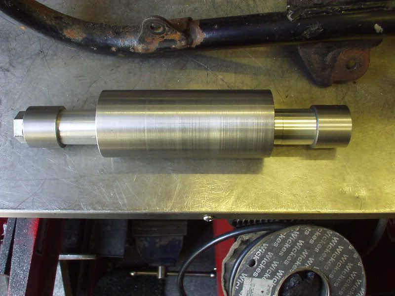 It also doesn't matter if I tac weld the guide tube in place slightly off center as everything moves in the guide tube for me to align the new bushes perfectly in the frame. 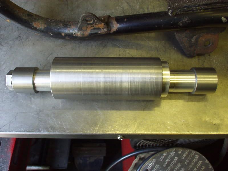 This is how the threaded end of the spindle will sit in the new steel bush. 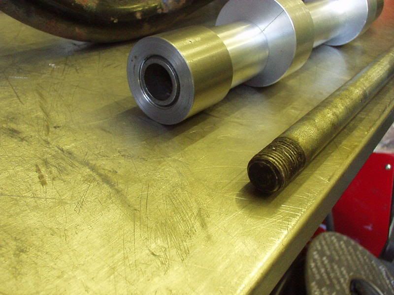 Hell Yeah ! What's better is that by getting new inserts made for the guide tube I can use it on most bikes to replace (& move) different sizes of spindles. |
|
|
|
Post by captain chaos on Aug 6, 2013 19:37:32 GMT
by joves i think i got it ,well not realy ,but i do undrstand you ,when will you post the pic of the drilled pivot??? so wat grade of steel are you useing for youre braceing??? Should start on that tomorrow, stripping bottom end of engine today & currently having fun getting the rotor off. Using the swingarm spindle slide hammer method but if it doesn't work I'll see if I can't scrounge a rotor puller later. The simple answer for grade of steel I use (tube) is CDS (cold drawn seamless) aka CFS (it's new name) with NBK (normalised) being good if your going to be bending. Most places look at you blankly if your asking for CFS NBK but understand CDS. There has been mucho debate on here prev about ERW tubing which is seamed, depends who you talk to but many would not use ERW when building a frame. However cut your stock frame up & you will find seamed tubes. Theory being that the tube may be brittle adjacent the welded seam so thought needs to be given as to the seams postion. Maybe the Japanese factories understood the limitations of seamed tubing better & so were able to use it. Others might say they got away with it. My take is that I would only use CDS (seamless) for structural main tubes but I would not have a problem using ERW for additional secondary bracing tubes although it wouldn't be my first choice. |
|
|
|
Post by captain chaos on Aug 6, 2013 19:39:44 GMT
i love effer motors but GJG posted an interesting thread about the benefits of oilburners Yes I did read some of the banter between GJG & SSR in that, interesting thread & I have an 1127 sitting in the lounge waiting to be mated with a slabby 7 frame. Anyway back to the proper Old Skool Suzuki AIRCOOLED 8v motor Slow frustrating day but mostly bagged & tagged, got a bit too late to start pesuading crankcases apart, job for tomorrow. 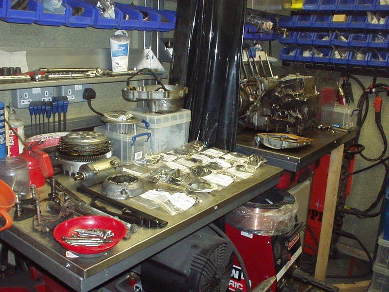 |
|
|
|
Post by captain chaos on Aug 6, 2013 19:42:18 GMT
Ooopps looks like I've stitched myself up working on the others bikes with the OSS party not far away.. PeteG's bike yesterday. 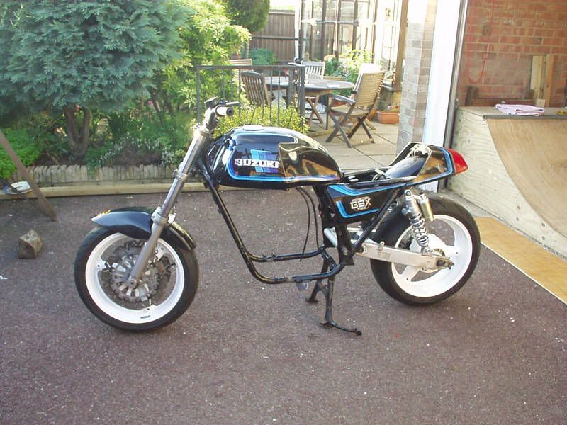 My bike today 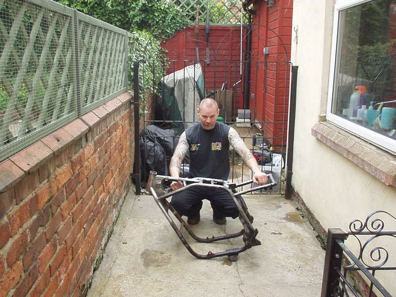 If I start walking now I should get to the party whilst there's still beer left and look no F**king top box needed  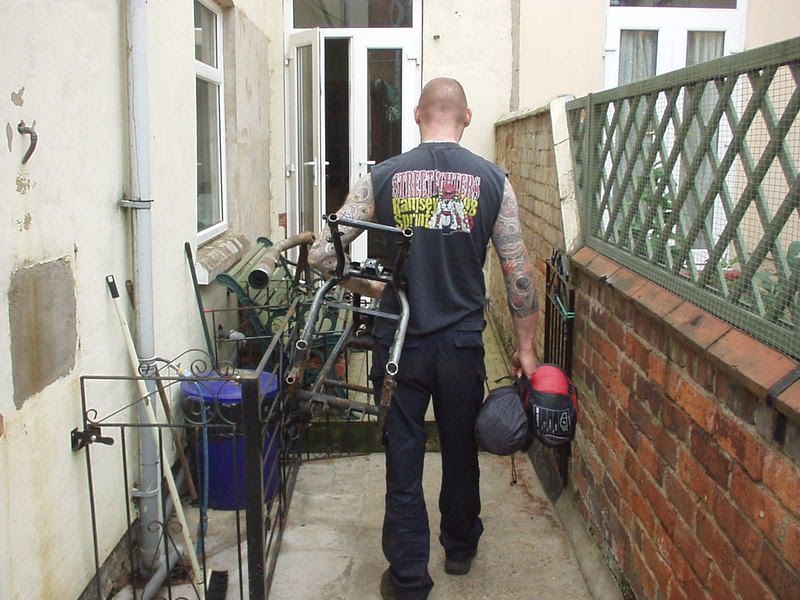 |
|
|
|
Post by captain chaos on Aug 6, 2013 19:48:17 GMT
Got the cases apart earlier this afternoon & all looks to be well in there, going to get the crank checked over & the clutch basket / backplate sorted properly (see my post in Aircooled for more on that). 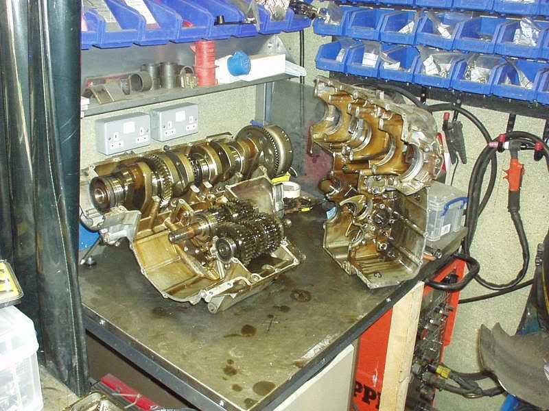 Think that yesterday was the low point of the project so far for a cpl of reasons, even though it looked like shite when I got it.. 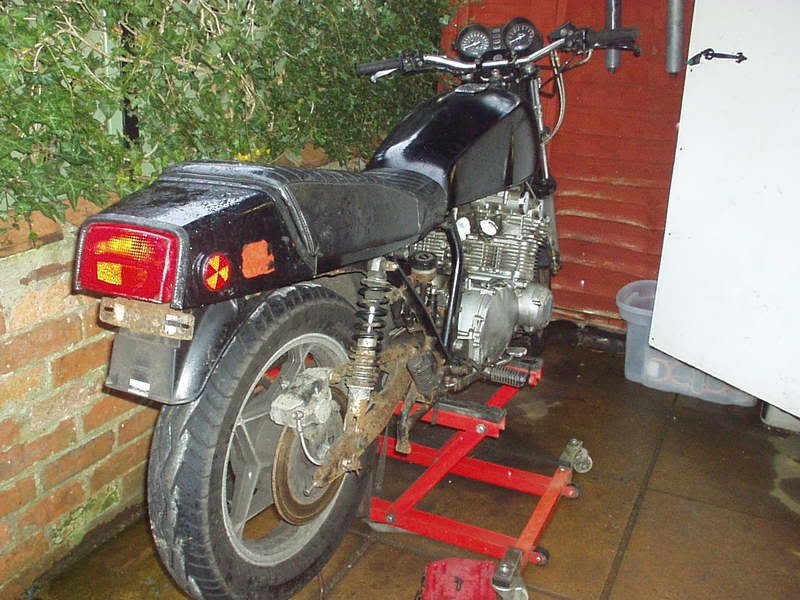 Sorting bikes like this out normally means stripping them bare before you can bring them back to life and with my frame looking like this (no real work only bits cut & ground off) & the engine spread all over the bench I think this is as bad as it can get. Felt knackered from doing the hours to finish PeteG's ET & in truth outside my comfort zone stripping down the engine, done plenty of 350LC's but the GS is on a different scale. Still get stuck in is what I say & if you have a go you also shouldn't be scared to ask advice when needed so thanks to everyone who answered my questions up in Aircooled. Right enough of that. Stuck the cases back together with just the gearbox output shaft in place so easy to take engine in & out of frame to check chain alignment. Confirmed a suspision I had, on Stevea's Road to Ruin Kat we ended up with a 5/8th offset front sprocket + making a longer than standard spacer that sits behind it, which gave this chain run, see where it runs in the chain cut outs a did.  Where as a similar (but prob not exact) mock up on the GS still has the chain run not touching the frame tube. 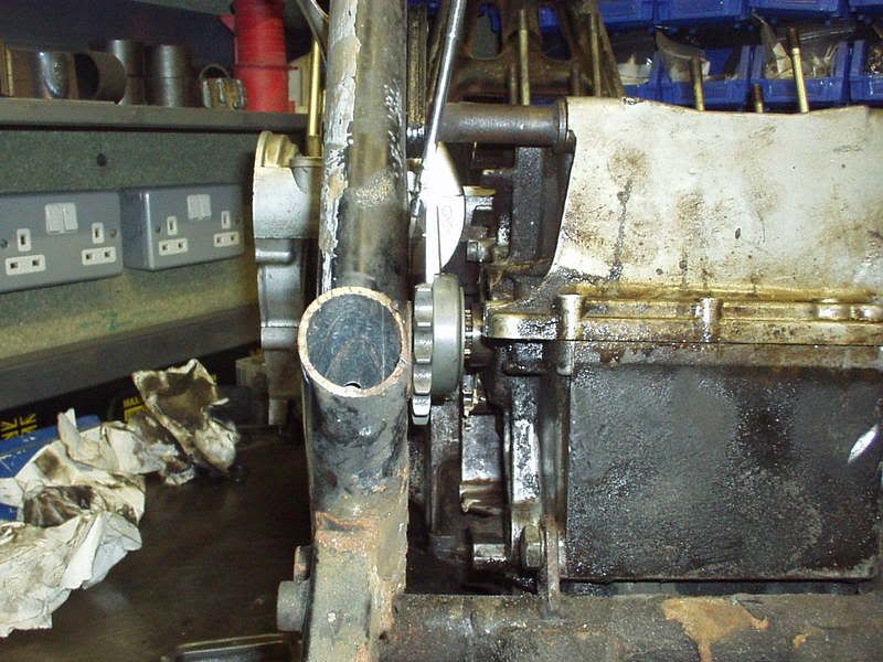 Here you can see how far off the stock spacer the 5/8th is sitting. 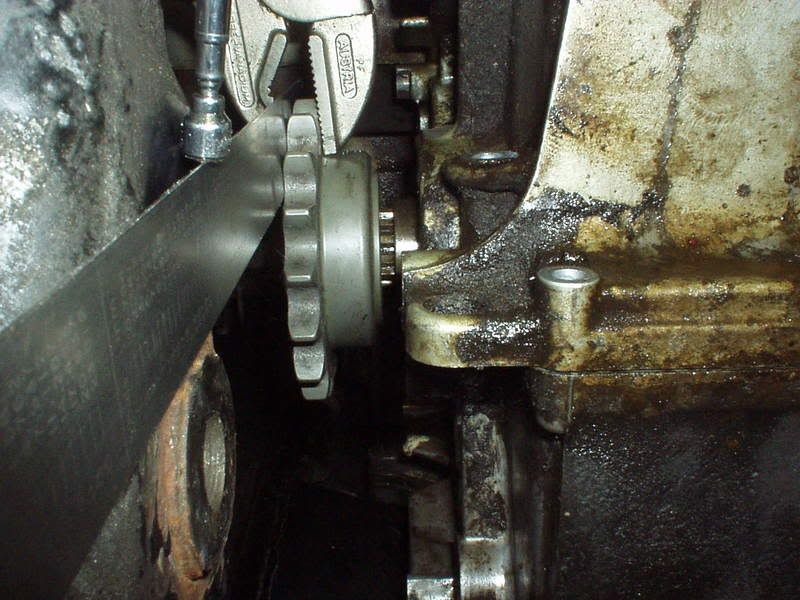 With the face being at the end of the splined section. 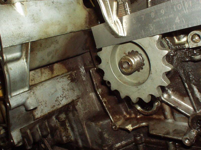 Will prob go down the outrigger route for this, I've got the write up BBK did for his homebrew version on his EFE BUSA so might do that. Depends where I'm going to run the chain, which means getting the new swingarm bushes fitted. First thing in the morning I need to build it as rolling chasis to check a few measurements & then I can get stuck into it |
|
|
|
Post by captain chaos on Aug 6, 2013 19:54:01 GMT
Had a measuring setup kinda day, not everyones cuppa but if someone says 'why did you do that?' I want to try & back it up Going back to this earlier pic & the big difference in fork lengths 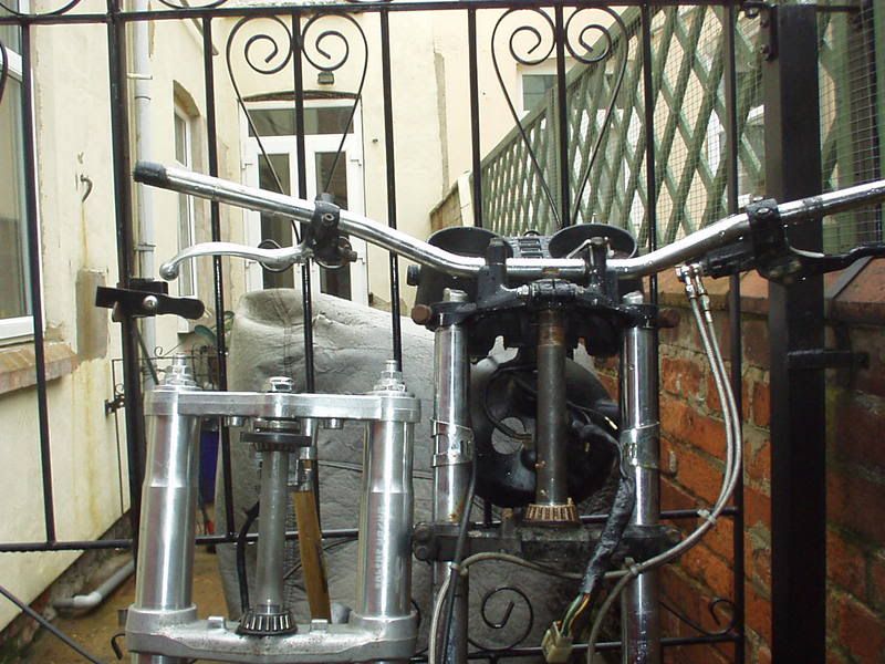 A lot of peoples first reaction would have been that'll never work but I've been convinced it will, maybe I'll have to change that opinion once it's been thrashed round the twisties but worst case it needs some slugs in the top of the usd's. Here's the low down. Stock GS1000ERake 27 deg Trail 116mm Wheel base 1505mm Source Suzuki workshop manualGrebRodRake 22 deg Trail 83.5mm Wheel base 1460mm Clearance to bottom tab on oil filter housing 235mm @ swingarm angle 12 deg giving chain clearance over front of arm Fork offset 35mm (SRAD750 yokes offset between steering axis & wheel spindle) Trail calculated using Tony Foales software & the measured values
rake 22deg, fork offset 35mm, front wheel rolling radius 300mm(Buell's 2008 1125R Rake 21 deg, Trail 83, Wheel base 1385mm) My top shock mounts are going to be adjustable so I will be able to dial the swingarm angle shallower which will increase the rake & trail if stability is a problem. 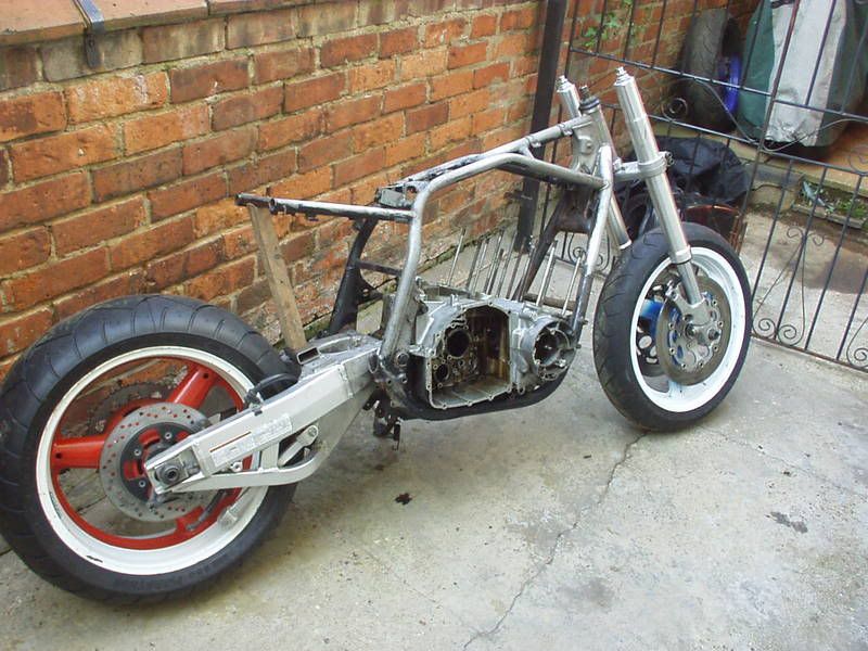 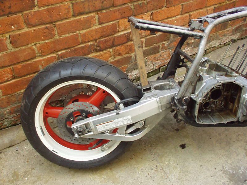 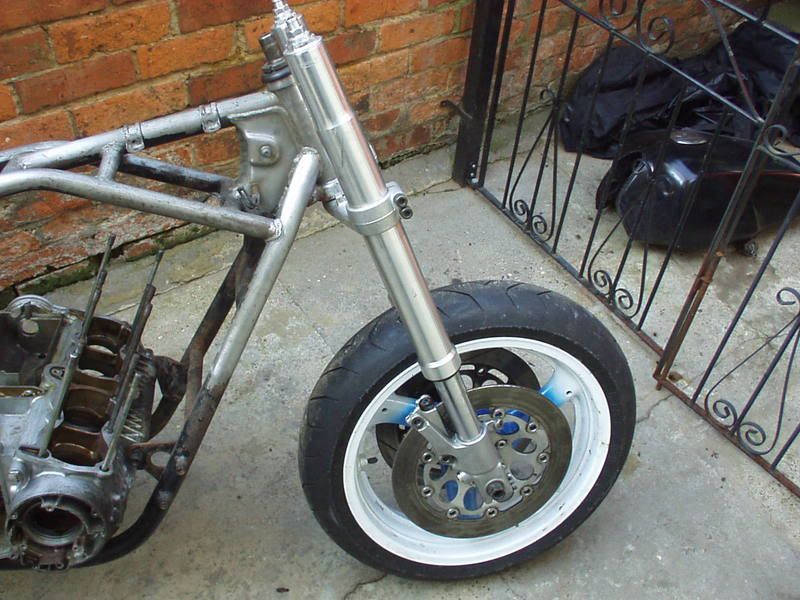 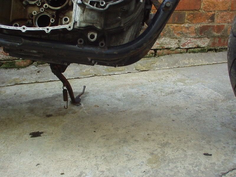 PeteG was glad he dropped by 'hold this level a minute just got to measure a few things' Still he was after borrowing special tools & nothings free This is a close up of the TLR arm into a GS frame hitting the engine problem. Remember that I have ground a bit of the arm away to just get the 16mm GS spindle through. The TLR arm has a 25mm bore, math being 25mm - 16mm = 9mm divide that by 2 = 4.5mm, so as it sits with the TLR arm as far back as it will go in its bore against the 16mm spindle I would have to be able to move the arm forward 4.5mm to use a 25mm spindle in the stock bush location. No can do which is why I'm going to move the pivot 6mm back. 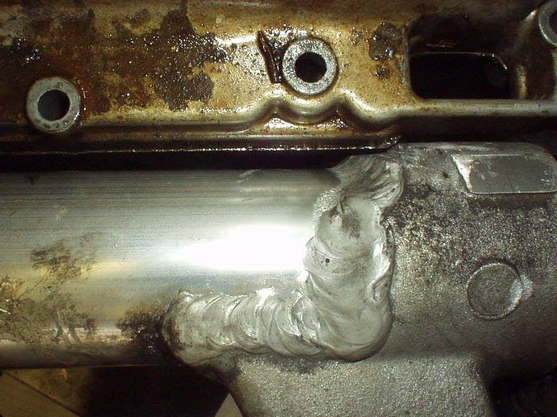 Thought I was in luck today with a rear disc from the store in the loft. 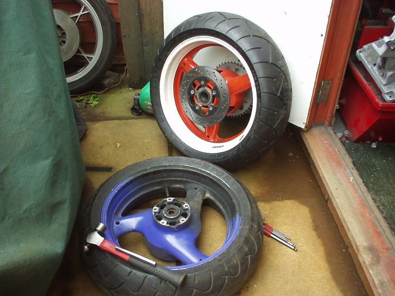 Didn't quite get away with it. 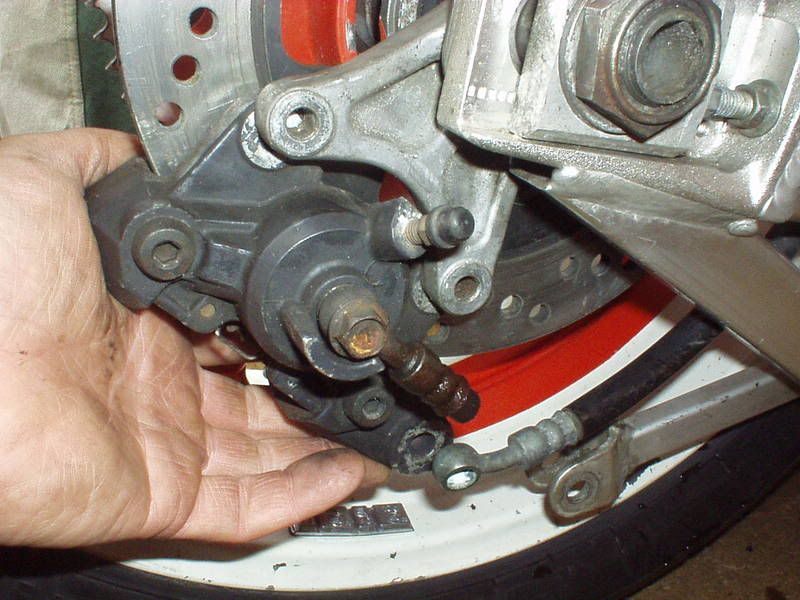 |
|
|
|
Post by captain chaos on Aug 6, 2013 19:59:08 GMT
I dont think its the handling thats the issue here, but the clearance. When I chatted to BBK about it he said with the shorter USD forks on a GS frame your collector box will touch down thru the corners lifting your front wheel off the ground..... I wanted to know where the rake & trail was at for stability, got tank slapped off an RD400E breaking both elbows, wrist & foot Whilst at the racey end of the scale should be cool. Did read & take note of BBK's comments on clearance, have a flat collector to use Bit of late night stripping. 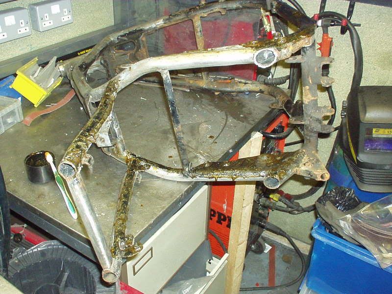 Lots to do but getting there. 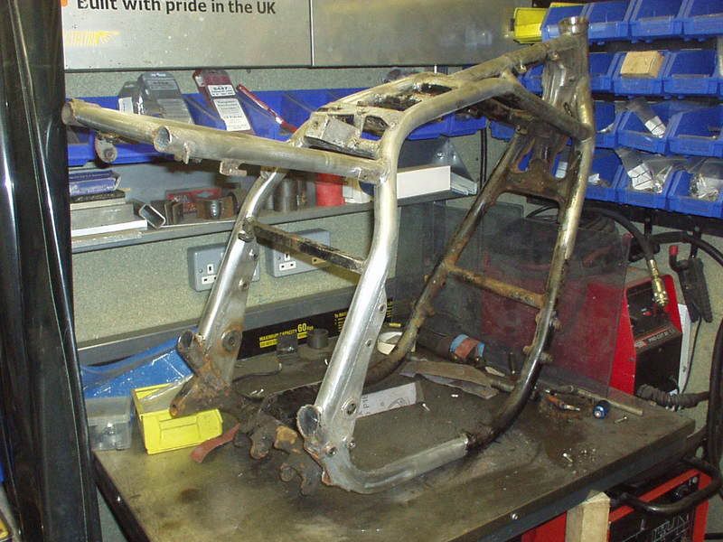 |
|
|
|
Post by captain chaos on Aug 6, 2013 20:01:00 GMT
Trail at 83.5mm is a very low number. Read somewhere (maybe T.Foale), that the best (read: most stable) numbers are around 100mm. In his latest book he does an experiment where he built a variable rake front end (no fork offset) to test trail values between 50mm - 100mm. He concluded rideable over the full range, lower range front end livelier & more sensative to bumps, upper range very steady but could still be manoeuvred quickly. (that's a very short summary of test). He feels that current rake & trail figures are not that adventureous but does point out he is concerned with general rideabilty & not ultimate performance such as on a race track. My view is that GrebRod's front end geometry is behind that of what Buell think is safe to run on mass produced bike & with the GS going to have a braced frame (less flex esp when running radials), new wheel & steering head bearings, etc (as a lot of handling probs are caused by things just being worn out) I'm prepared to stick my arse on the line & ride it. Good to question what works & what doesn't esp as the newer front ends tend to be shorter (& good to question me as I might be missing the point). Worst case I slug the usd's which increasese rake & trail. |
|
|
|
Post by captain chaos on Aug 6, 2013 20:04:05 GMT
Less bollocks more work I hear you Did a bit of prep before I start on the new swingarm bushes. In amongst all the grease, rust & shit I unbolted part of the one of the largest (non Harley ) side stand supports in the world.. 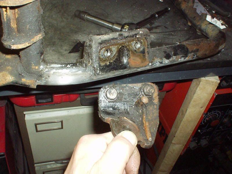 Next I looked at this lot & decided I better tidy some of it up, great way for making the clock fast forward, but not in a good way, time consuming or what. 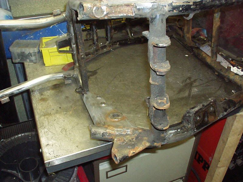 Worth it in the end, big difference 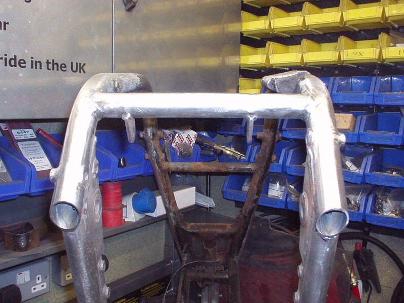 I find helps to hold the frame very steady when doing that sort of stuff. 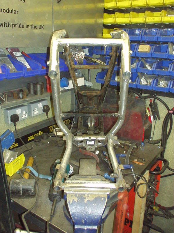 Re CDS / ERW chat earlier in this thread, main tubes as can be seen are ERW. 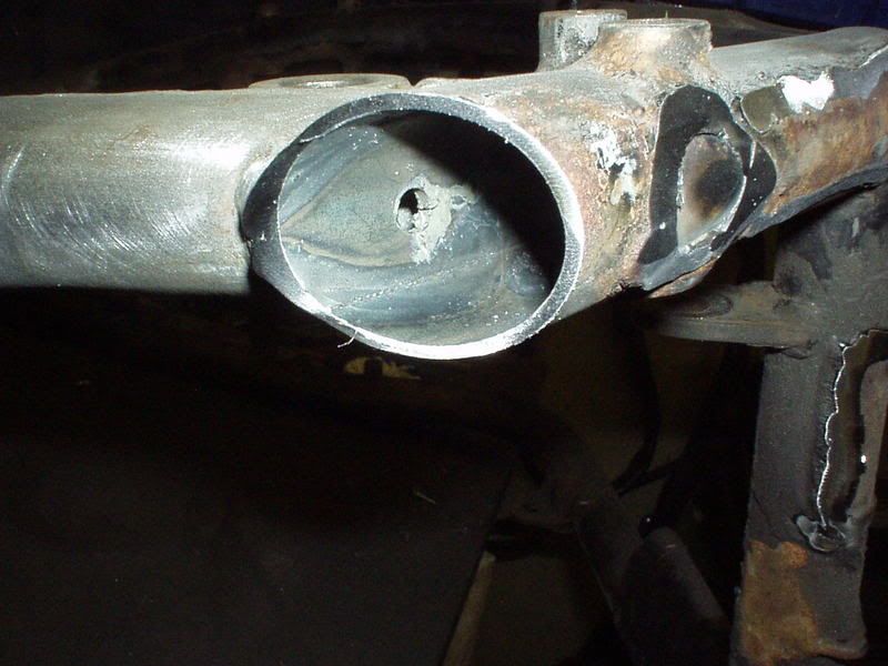 Kettle then start setting up for swingarm bushes. |
|
|
|
Post by captain chaos on Aug 6, 2013 20:09:08 GMT
Swingarm bushes, the time for talk is over. (There's a couple of pages earlier in the thread explaining this method if your interested.) I'm going in Difference in size between 16mm GS & 25mm TLR spindle & bushes. 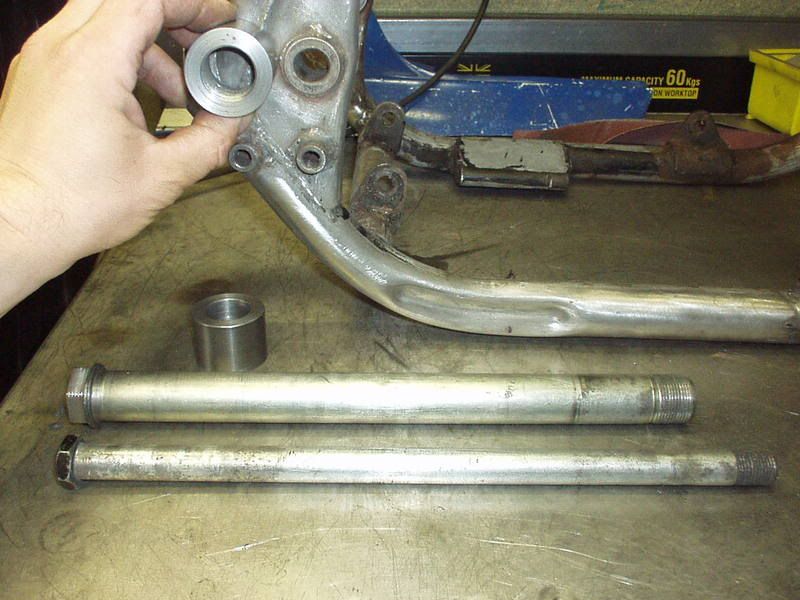 Here's my steel Guide Tube with alloy inserts drilled central 16mm for the GS spindle. (aka the 16mm setup). 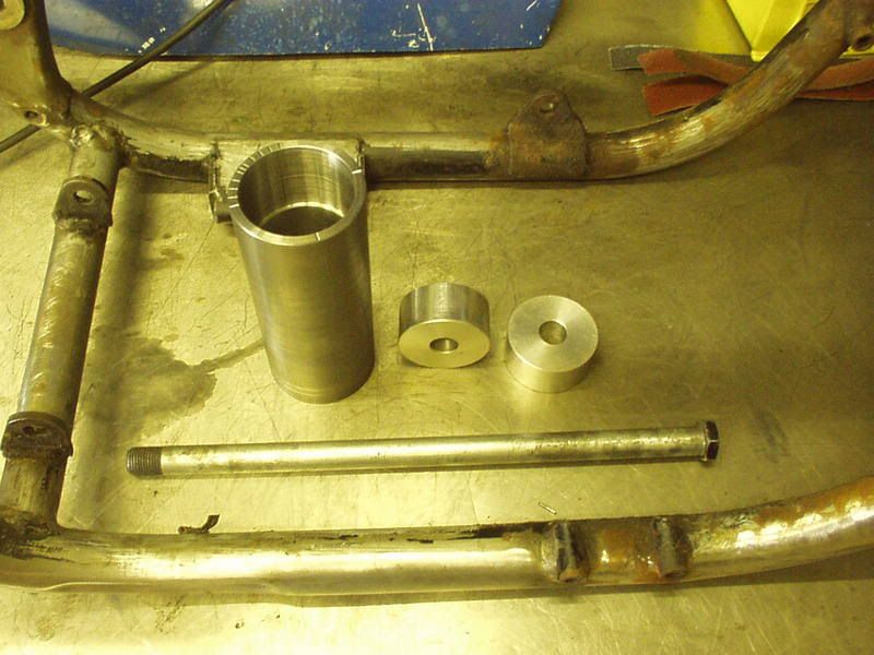 As I'm going to move the spindle up & back I need to set the frame up level, here the Guide Tube is threaded in place on the stock 16mm spindle & is level. 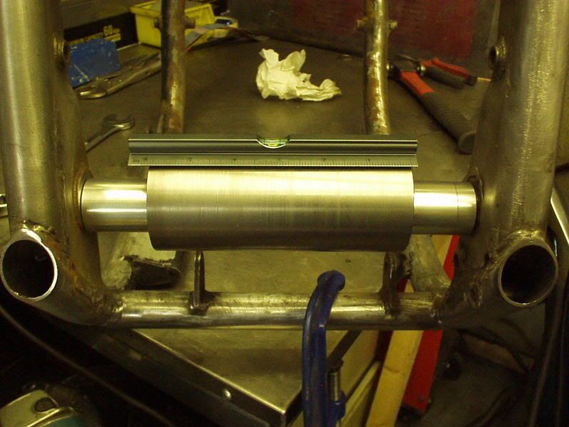 The G Clamp shown in the pic above was excellent for fine level adjustment & here you can see the bottom down tube is also level, shimmed with cutting discs. 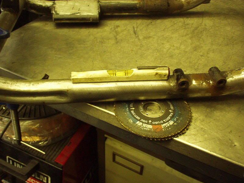 Spindle going up & back & The Guide tube has one quadrant marked at 10 deg increments & also 45 deg, I need this quadrant to be in the 9 o'clock to 12 o'clock position. 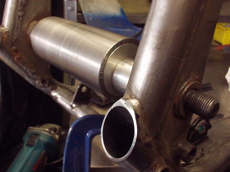 To make sure 0 deg was accurate on the dial I set up a straight edge & rotated the Guide Tube until the measurement at 0 & 180 deg (aka top & bottom) was the same to the straight edge.] 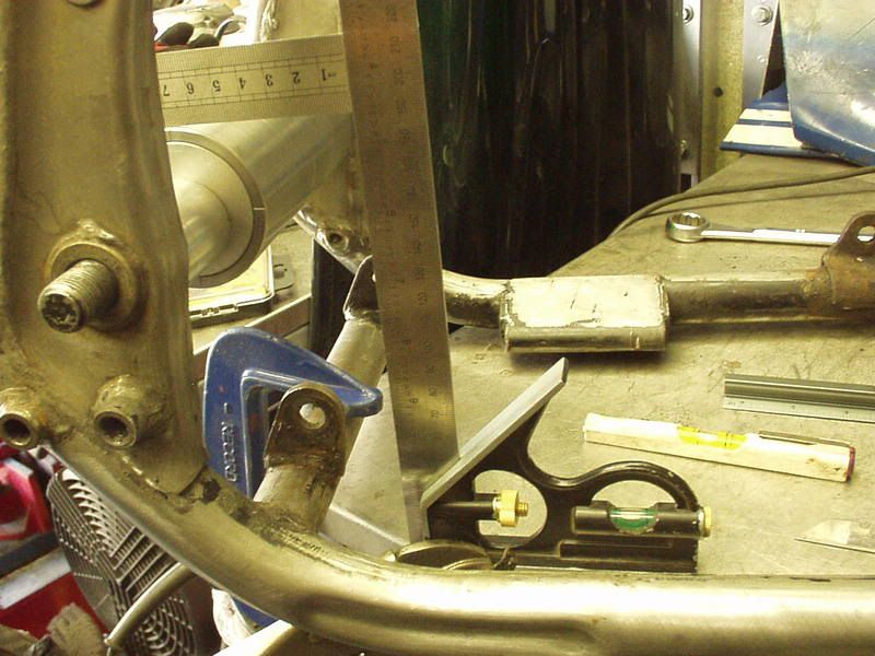 That done time to weld the Guide Tube in place (temp as will be removed once the new bushes are in). Sorry Richiemouse did think about clamps & that but the tool is a means to an end & welding is quicker & more unlikely to get moved. I can easy clean up the Guide Tube later. 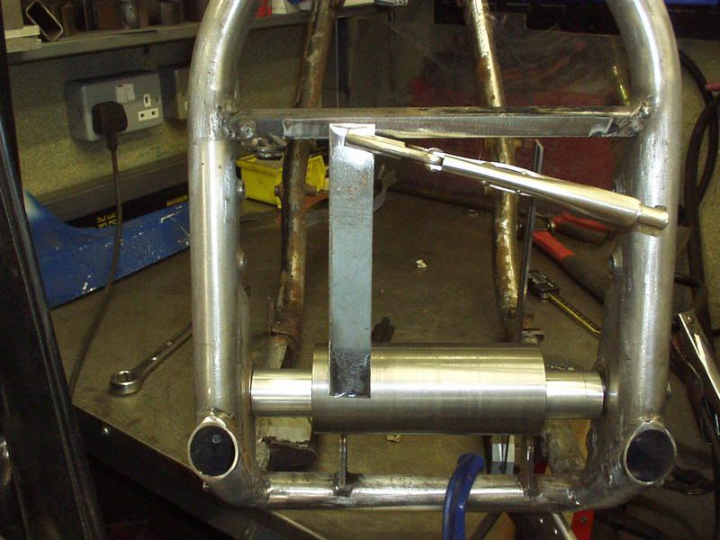 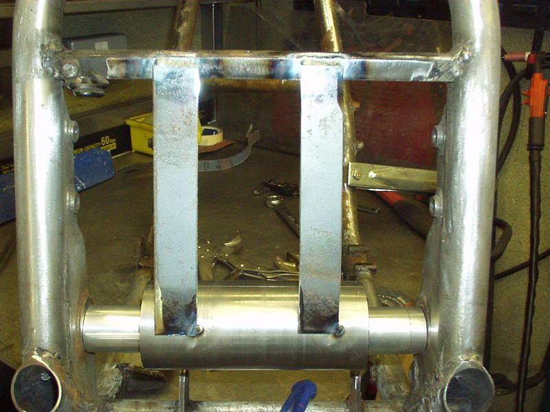 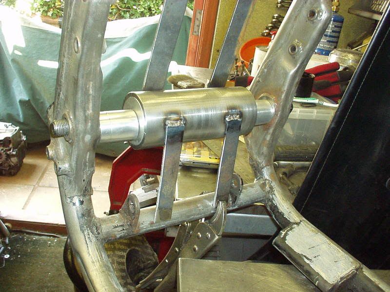 This shows all the supports fully welded & the alloy inserts with the 16mm central holes removed. The Guide Tube is the jig for the original spindle position & I'm ready to look at removing the existing bushes in the frame. 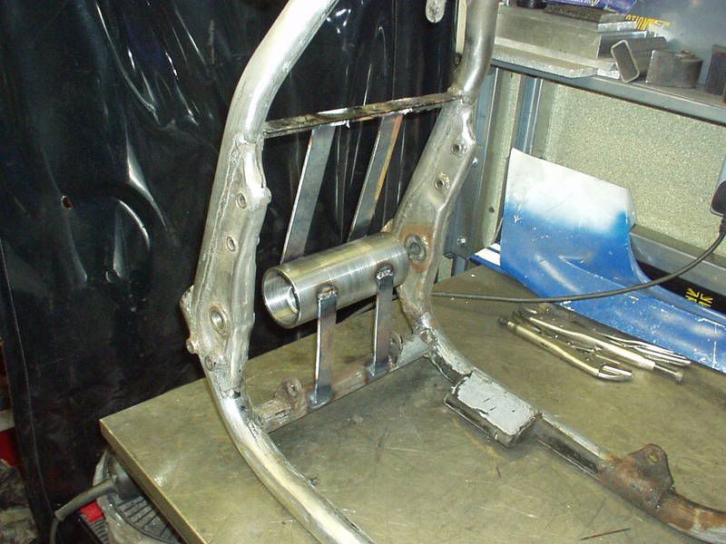 Using GJG's method I have some steel 16mm inserts made up with a 1/4" hole as that's what my hole saw system uses. GJG used a 1mm pilot, not sure if it makes a difference with accuracy but that isn't really an issue in my case as I'm drilling 35mm holes & then by other means taking them out to 40mm. I can afford to be less accurate in intial cutting out as the Guide Tube is very accurate. 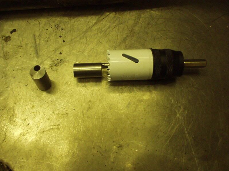 The pilot is off center as far as possible & as I will be moving the pivot 6mm back & 6mm up I have set the bush at a 45 deg angle using a line that had been scribed on it & then it's tac'd in place. 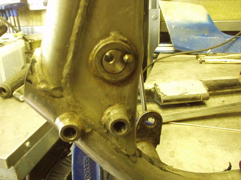 Other side done as well & a bit more welding as I don't want the inserts to break free during the drilling process. 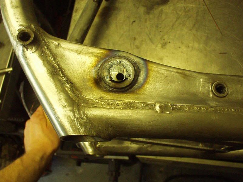 Off to drill them out then |
|
|
|
Post by captain chaos on Aug 6, 2013 20:13:22 GMT
Drilling out bushes, first one piece of piss took about a minute 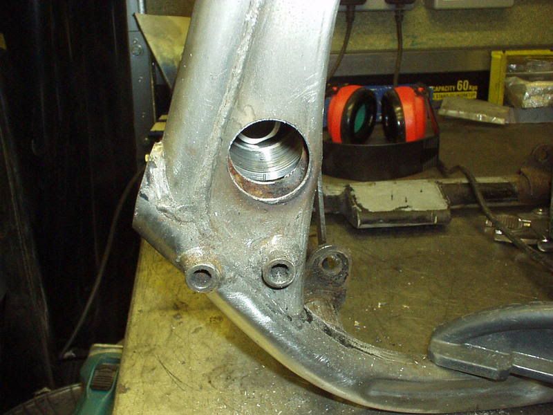 Other side gave me grief & ended up killing my drill but it was old & what a way to go, working on GrebRod 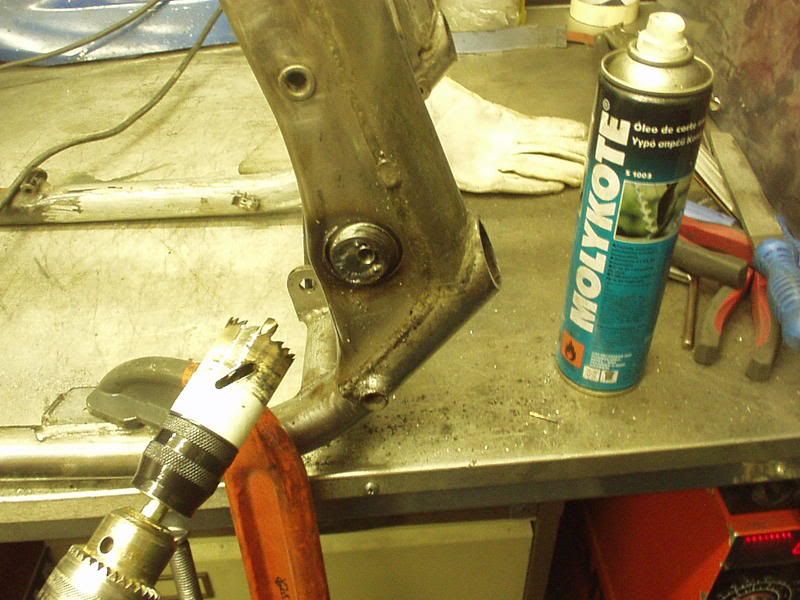 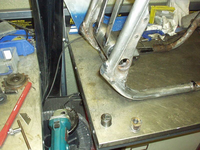 The difference was this. The existing bushes are like top hats with the shoulder on the inside butting up against the frame & welded, which is why they look bigger on the insides. On the easy one I had ground that back to the frame but as the shoulder had gone completely there was now nothing holding it in place other that the front weld. Hmm, ok as I was drilling from the front as soon as I had broken thru my pilot hole would then be useless (as the bush would be 'free') for the rest of the drilling so I re tac'd the back in place to hold the bush till I had gone all the way thru. On the harder side I left it with plenty of shoulder on the inside face which is where the drilling thru became a ball ache. My advice would be if you do any of this to remove as much of the shoulder as you can on the insides with a grinder, leave almost nothing but don't totally break thru all the weld & grind it flush. Also watch your wrists from drill torque if the bit sticks. Due to the above 'mini saga' I would not now be confident of accurately aligning my new bushes if I was just relying on the accuracy of the holes drilled. This is though why I thought up my Guide Tube method as it matters not that I had a bit of grief getting one of the bushes out. Respect though to GJG in his "GJG Katana GSXR rebuild 2008" project as he drilled his out accurately (30 mins a bush ) & got his new bushes in purely on the accuracy of the drilled out bushes (albeit with a smaller 20mm spindle). I can't tell you how much thought I put into my Guide Tube & the calcs for relocating the bushes but these pics will give you some idea. First up, here are the 'new' alloy inserts for the Guide Tube drilled off center with the 25mm TLR spindle size, shown against the 16mm inserts for impact. Off center as the TLR arm hits the engine in the existing place. 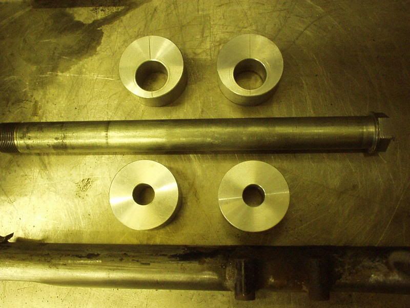 6mm back & 6mm up, using the right angle triangle formula of A squared + B squared = C squared I worked out how far off center the 25mm needed to be drilled & because A & B were equal 45 degs it was. Guide Tube with 25mm inserts, dialed in at 45 deg places the spindle in its new location. 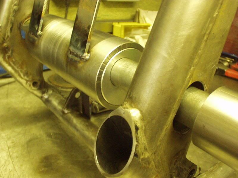 This shows how big the bush is compared to the hole I drilled. 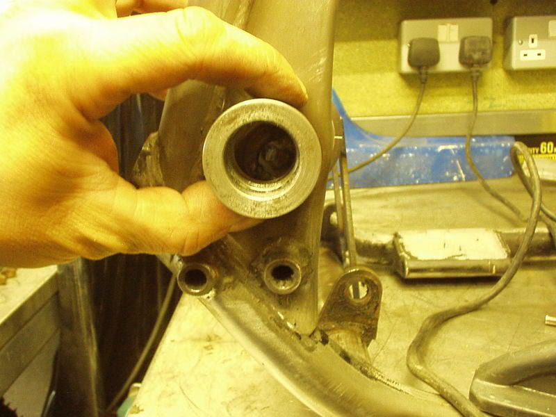 but because it is offset the bottom right edge is where the existing bush was. 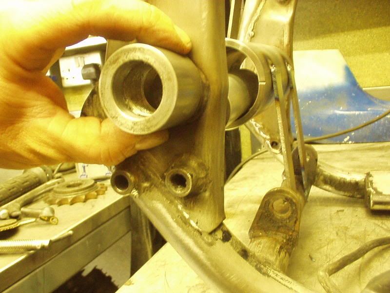 Which is why I could only use a 35max holesaw because I could only offset the pilot hole so far in the 16mm inserts that I welded in to the existing bushes. Any larger holesaw & the resultant hole would be too big here. 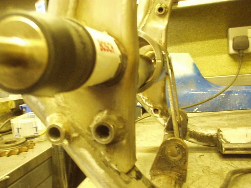 New bush slid onto the end of the spindle I can then slide it up to the frame & scribe around it as I guide for making the hole larger. 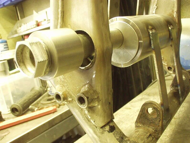 Lots of calculations to get the sizes & locations right as can be seen from these two pics. 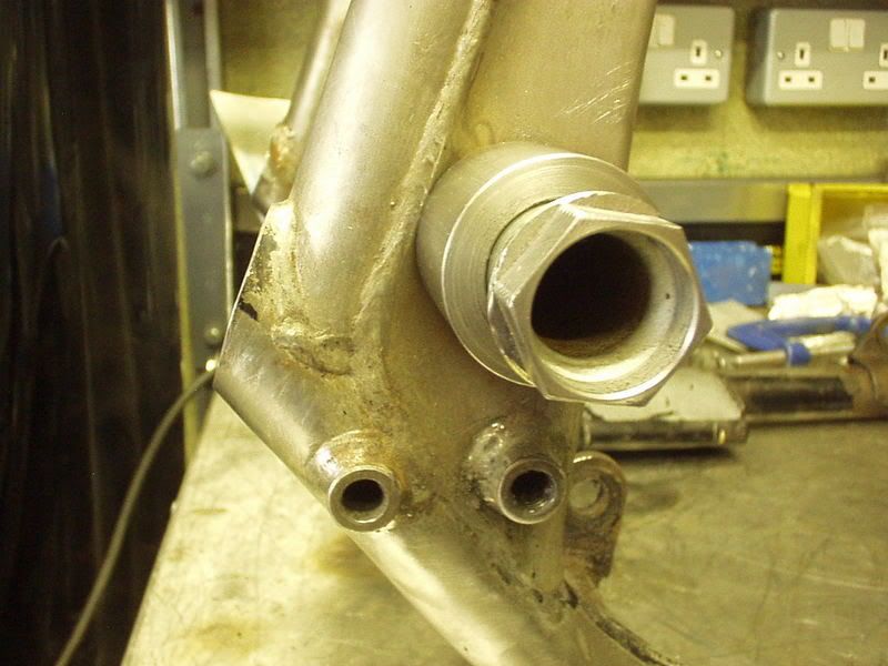 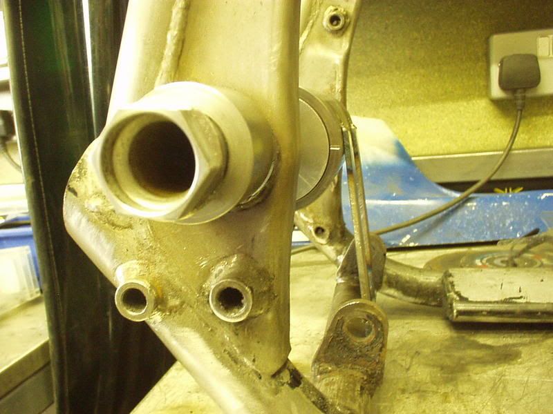 Big hollow spindles rock, no sleeving bushes here 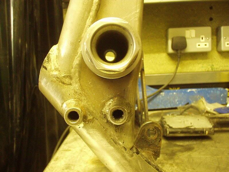 |
|
|
|
Post by captain chaos on Aug 6, 2013 20:21:50 GMT
Worked till 2am Sun morn opening the holes up, slept then had the rest of the day off  Here's where it's at. Gradual taking the hole out. 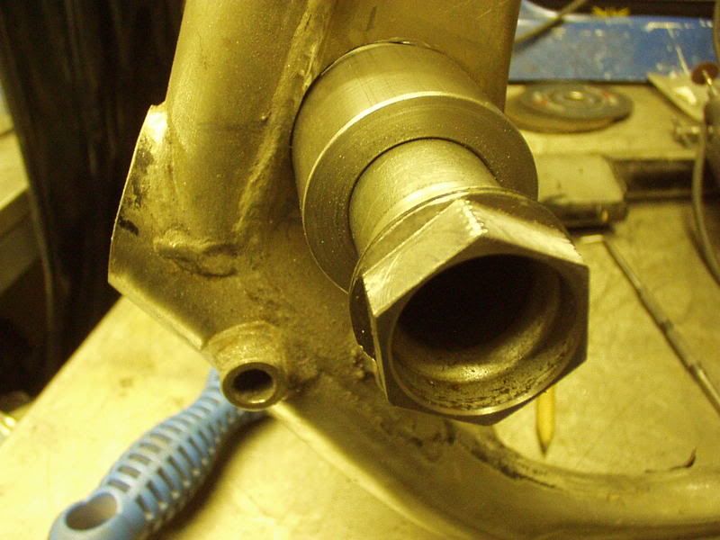 Fits all the way thru. 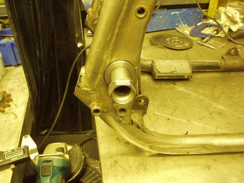 Did the other side as well, then for my next trick I had some spacers made that when in place on the spindle replicated the width of the swingarm. As long as I do the spindle up tight should have no probs when welding. 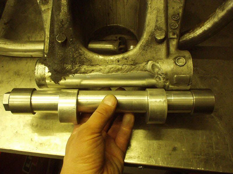 Don't need to run bearing end covers on this as one side is sealed behind the stock spacer & the other is a sealed bearing. 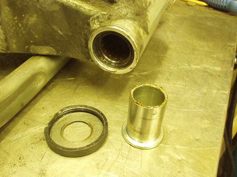 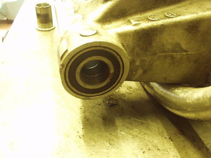 Last pic show's everything in place ready to weld, dialed in at 45 degs & central in the arm. 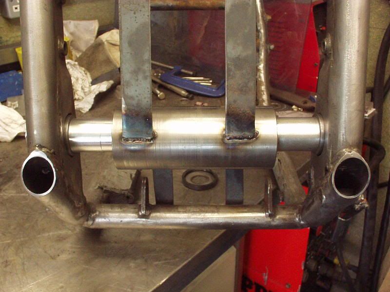 Busy with a few other things today so might not get chance to weld it up  |
|
|
|
Post by captain chaos on Aug 6, 2013 20:23:10 GMT
Got home from 'proper work' & got my arse back in the workshop to weld the new bushes in. Difficult welding in places, weld a bit turn the frame, how do I get in there... but looking good. Just letting it all cool down so I can cut the Guide Tube out & see if.. 1) the swingarm fits 2) it clears the back of the engine 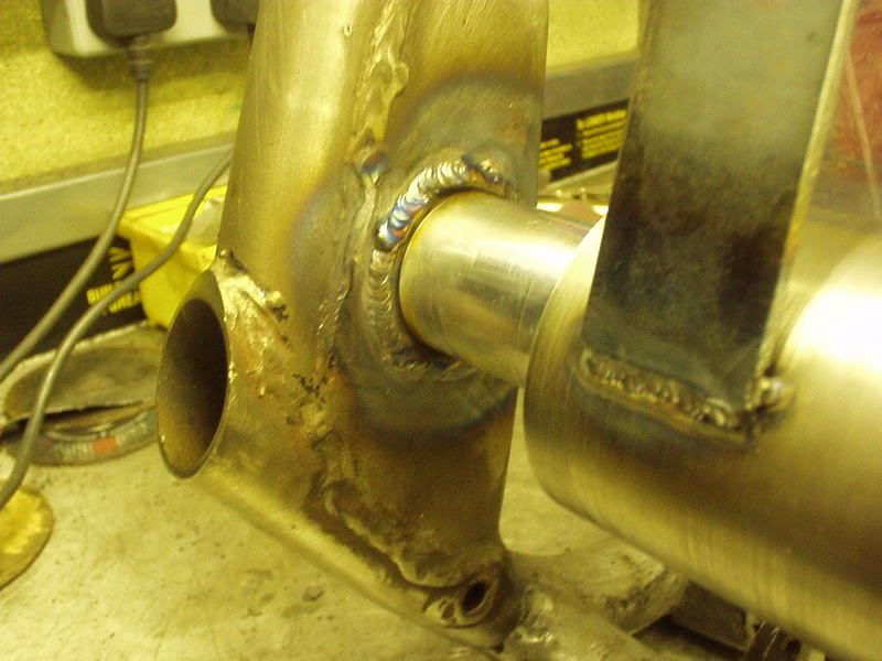 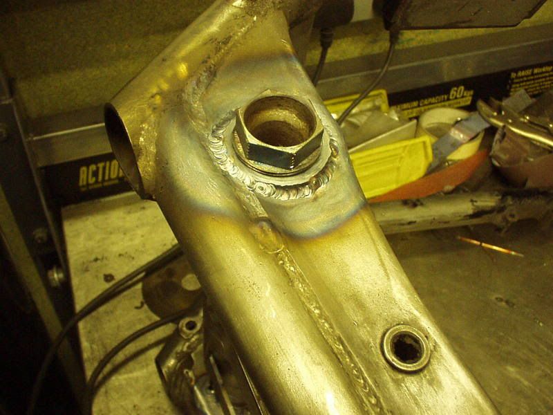 So did it work or have I just clowned myself online  First job was to see if I could remove the spindle, could have failed at this point but it spun out real nice (one of the new bushes is threaded). 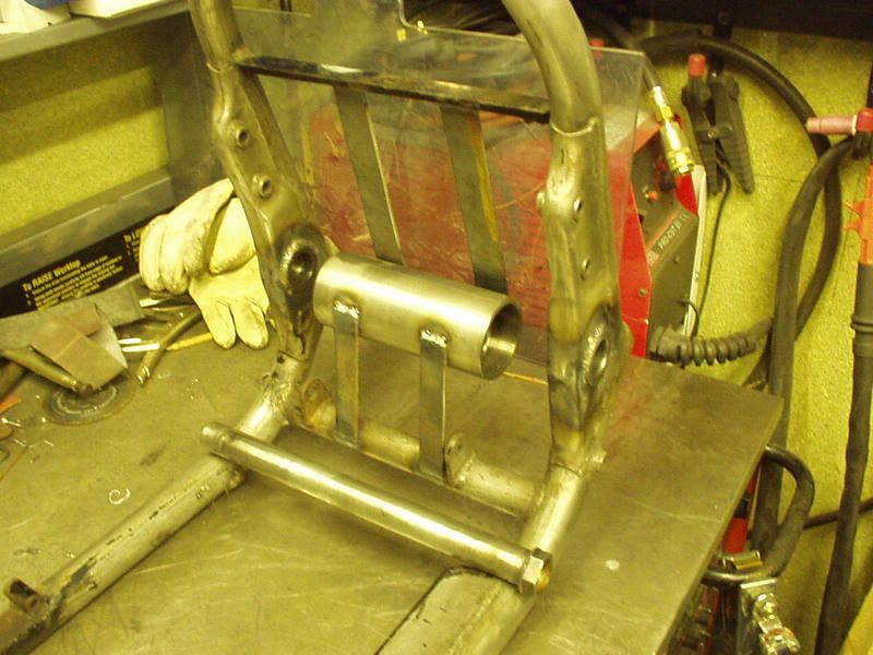 Next was to cut out the Guide Tube & see if the arm fits (without the engine). 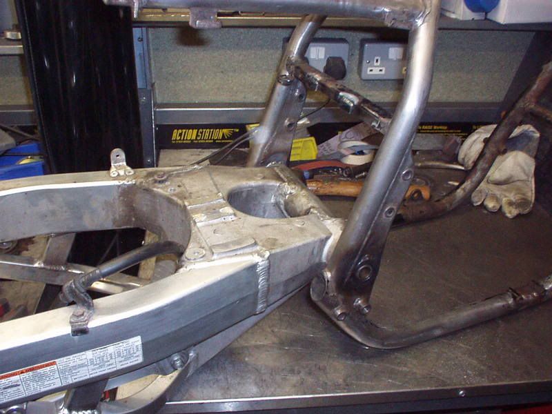 Looking good so far, now to try & fit the engine as it would not have been possible with the bushes in the stock location using the bigger spindle. It works you can see the 'clearance' between the back of the engine & the swingarm. 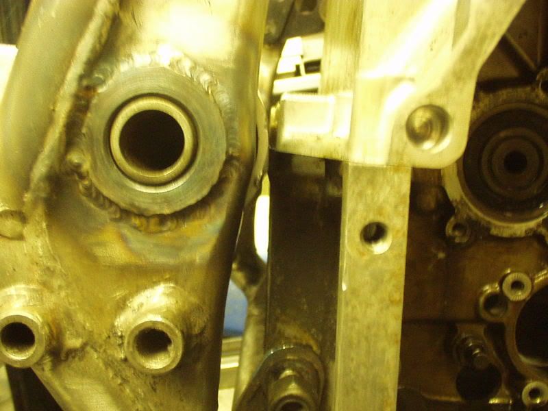 Just needs a slight fettle where I had prev taken a bit off during the mock up. It fits & moves up & down ok but ever so slight rub in one place. 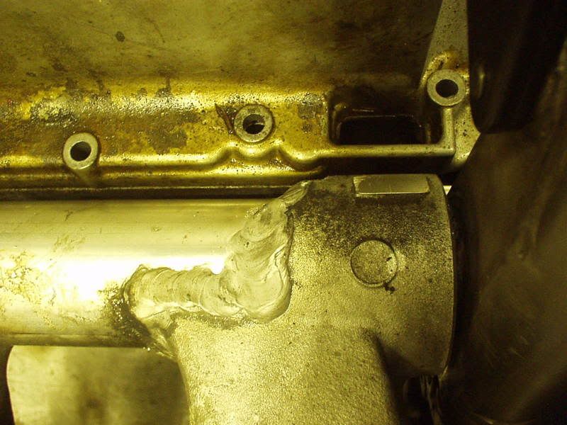 Proper job 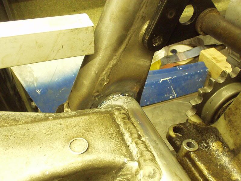 The stock 16mm spindle fits in the bore of the 25mm 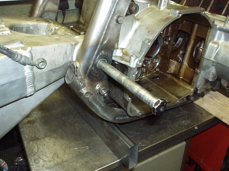 Couldn't resist sticking the 210 in. 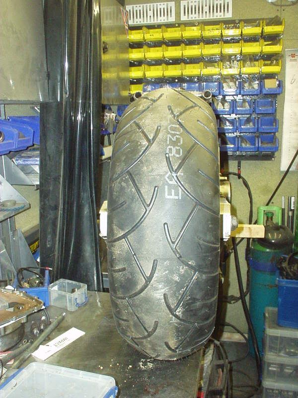 Doing a rough look at chain runs you can see that if I half tube the frame for chain cut outs the same as I did with Stevea's Katana 'Road to Ruin' project this will work no probs. 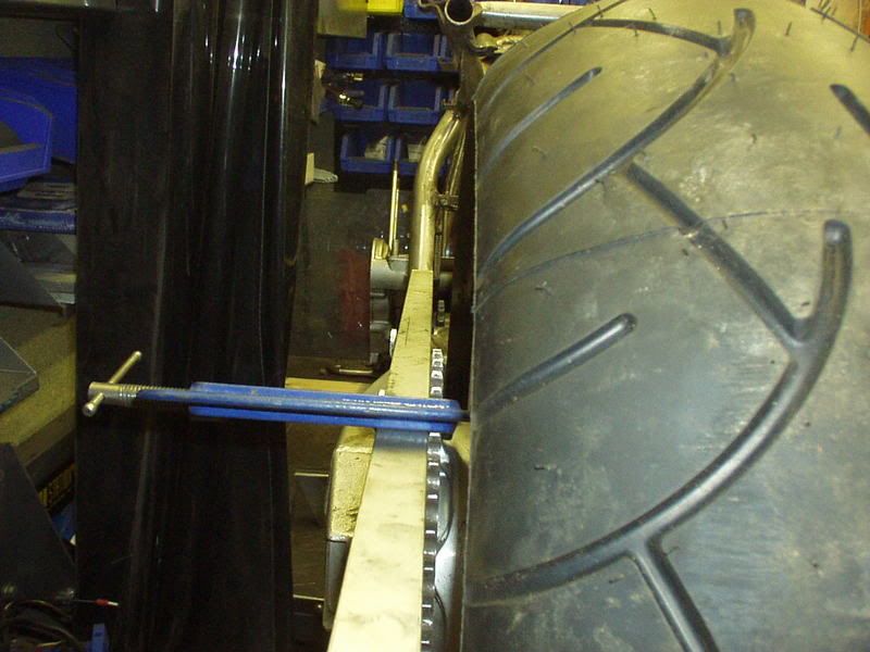 Love this pic, Hell Yeah !! Build it don't buy it 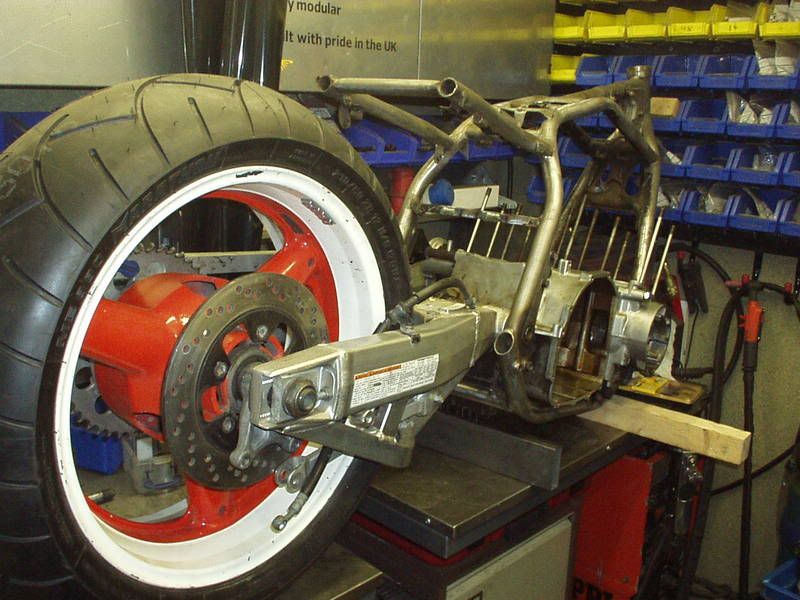 |
|
|
|
Post by captain chaos on Aug 6, 2013 20:28:47 GMT
Thanks for all your comments, glad you getting into it & it's only just started Took my crank to SEP Engineering in Kegworth (nr Donnington Park) today for a bit of truing, indexing & welding, estimated 3 weeks till I get it back which is after the OSS party so won't get to ride it there.. As long as I have the rear shock mounts down (so it's a proper rolling chasis) & a bit of bracing I'll bring it to the party in the Chevy im thinking of stopping the blade work on my GS1000S and going for a tlr jobbie looks bloody unreal mate. wat do you rekon dude? ? No regrets from me at all, it's a lot of work & the Guide Tube tooling I used to do it cost me quite a bit of money but I can use it other bikes so it's more of an investment. I wanted an underbraced arm as I'm using twin shocks & also an arm that had a 6" rim as standard to have the extra room across the wheel spindle to play around with 210 tyres. Using the 25mm spindle also gives me much needed extra strength across the pivot esp as I have removed the lower subframe tubes. I think it rocks esp as I when I look at it I know what went into fitting it. Top braced arms look cool with mono shocks but a bottom brace looks cleaner esp when you loose the bottom subframe tubes, this is my EFE project. 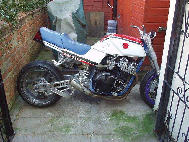 Which I might also bring along to the OSS Party in the Chev. |
|


