|
|
Post by captain chaos on Aug 6, 2013 20:30:46 GMT
Another late one last night, unlike me to do a mock up  Putting lots of bits together to test a few ideas. The exhaust that came with the bike was shite so had been on the look out for something else, PeteG offered me a mild steel set of Harris downpipes with the collector rusted out which I could have put some time into but I wanted stainless. Struck lucky on the evil place few months back winning a stainless set of 'one off' 4-2-1 downpipes & link. Got them out the box & fitted them yest eve & they weren't quite what I was expecting. Not saying that in a bad way, just expected then to be a conventional fitment running central & then the link kicked out at the right towards the back. Whoever made these put a lot of time into them as they fit so snug, oil & filter changes will be cool then... First pic I have been playing with tank angles to show engine off more but haven't finalised that yet. 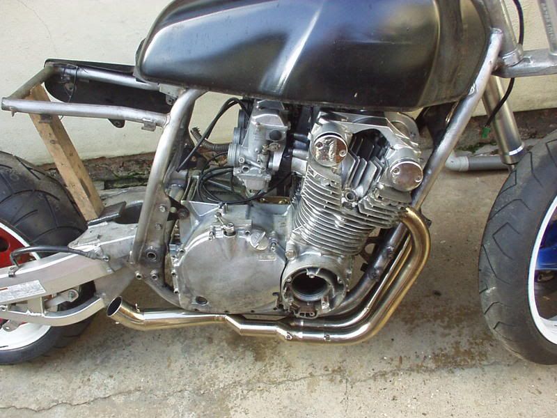 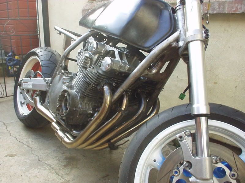 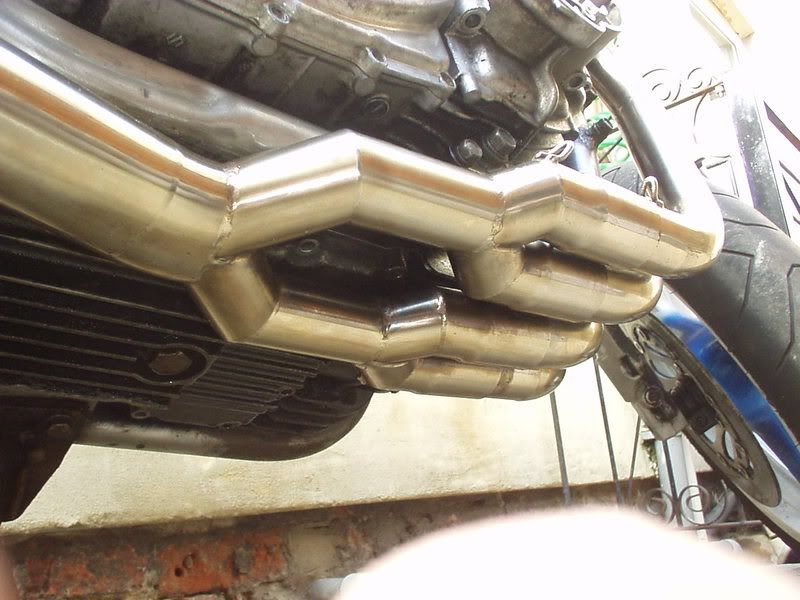 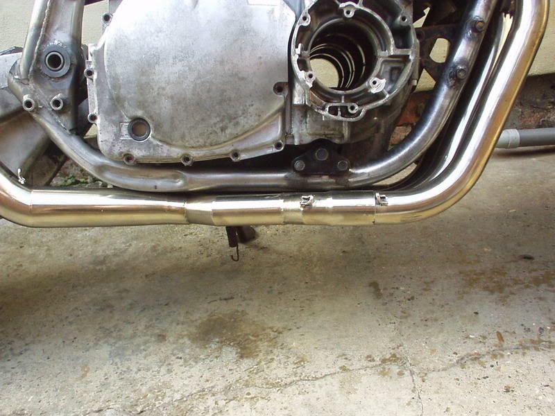 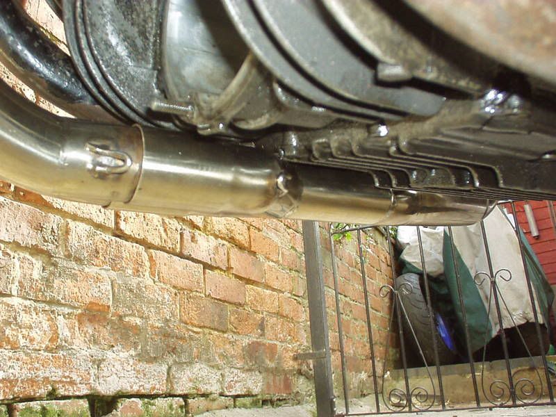 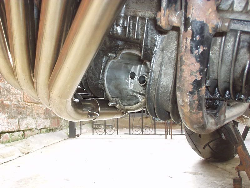 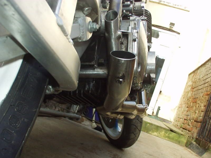 Need to change my plans a bit as to how I end the exhaust, got some good ideas. Right hand bends will prob be interesting.. Did lean it over to see how far before it touched but in the past haven't found that to be too reliable indication as doesn't take into account suspension travel. 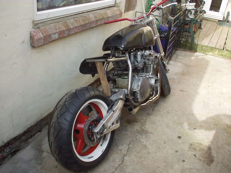 530 48 tooth rear turned up which means I have the correct size sprockets for when I do the chain cut outs in the frame tubes. 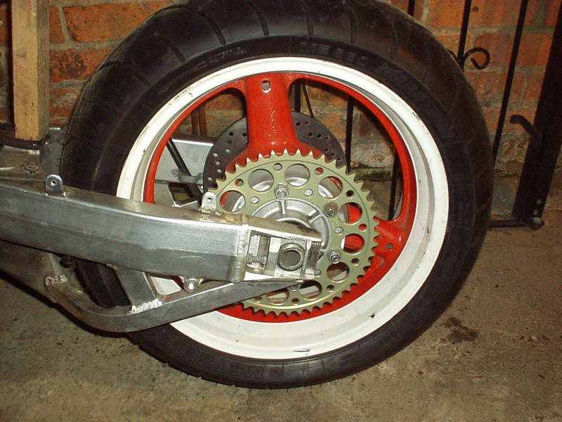 |
|
|
|
Post by captain chaos on Aug 6, 2013 20:33:30 GMT
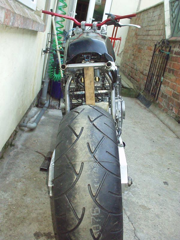 That got your attention  Looking good mate!!! Any idea who made those pipes? I likes them!!! What do you mean 'finish of the pipes'? Look good just as they are mate, an I bet they'de sound good!!!! Won off Evil place but I'll try find out who made them. Re finish I was on about (token) silencer as my plan if the link had been centralish was to run it up thru the 'mono shock' hole in the swingarm. Can't say exactly what I was going to do but it wasn't going to be underseat. As the link is way out right it might look too fusy if I 90 deg it back central to go thru the swingarm. Looked thru some Hot Rod mags today I got a few ideas. Been playing again. GrebRod hasn't got a typical UK tank & as it's an import (american I'm sure) I guess that's no surprise. Tried & failed to get a uk tank, no big deal to me as work with what you got & is a genuine GS tank in other parts of the world. What I'm not to keen on is how my shape tank leaves a big gap between bottom of tank & top of engine at the front when viewed from the side in a slope upwards kinda of way.  A uk tank being a different shape sits a lot flatter & if you look where the tops of the carbs are quite low. 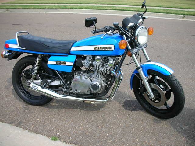 I'm all for changing the angles of things, bit here, bit there, as not many people do & it can give you a different look to what's out there. After raising the back, cutting out the existing frame tank rubber mounting points, putting a few flats inside at the front of the tunnel & taking a bit out of the frame tubes I got the tank levelish with the line on the cam cover. 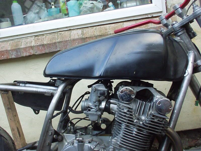 The side panel has to be higher to match (which I wanted) but isn't at a crazy Germanic angle either when it follow the lines of the new tank position. 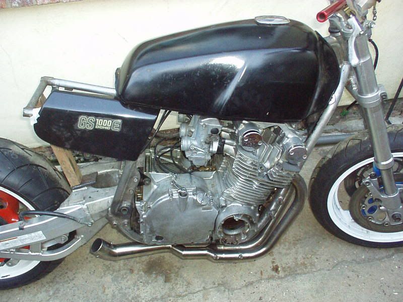 You can see from this pic by looking at the side panel area how much different this will look from standard as with the lower sub frame rails removed (new to be put in hidden by the panel) it will be very clean / minimal. 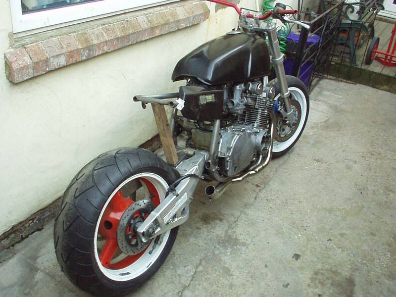 This is the engine vibe I wanted, more on display, the carbs more of a feature with the tank a little bit higher. 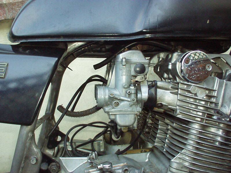 Another view from the back. Haven't checked that the wheel is central yet but looks out due to where I took pic from. 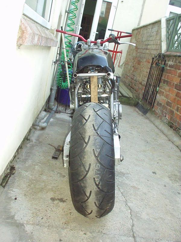 The most important thing I did today was get the last parts & hooked my Plasma cutter up to the compressor, as they don't like water I'm running an inline filter / regulator. Hell Yeah, Strangewayz has Plasma, not bad for a 8' x 6' shed 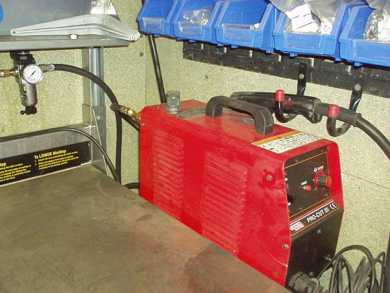 |
|
|
|
Post by captain chaos on Aug 7, 2013 17:30:40 GMT
. . . . . it's sunday afternoon . . . . I'm ready and very eager to read the weekend update Not as eager as I was to get stuck in but... Mrs Strangewayz went away for a long week end leaving me to 'entertain' the resident Dobermann.. Barking translated to wear me out walking or the furniture gets it  When I was free it bloody rained so couldn't carry on with what I needed to outside. Gave up & started to fix the Buell (weld up the bloody exhaust). Should be back on GrebRod Wed & then mad on it up till the OSS party. Here's a pic of my boy when he was younger, seats are the old bench out my Chevy, note the 'repairs' from chewing. Ending up with more camo than vinyl  Talk about make yourself at home 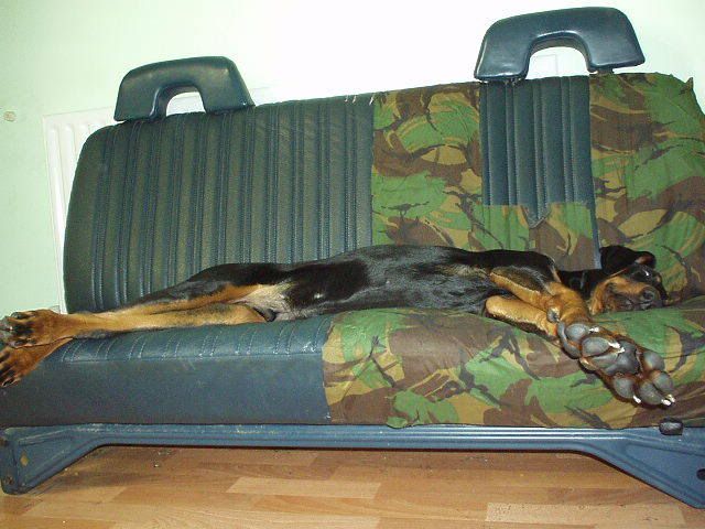 |
|
|
|
Post by captain chaos on Aug 7, 2013 17:32:51 GMT
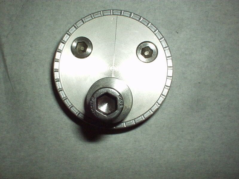
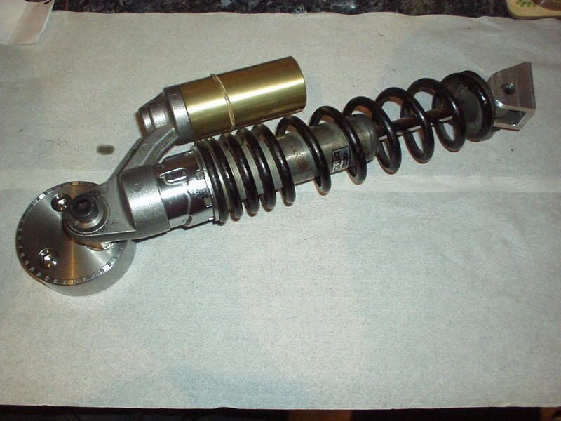
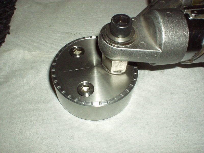
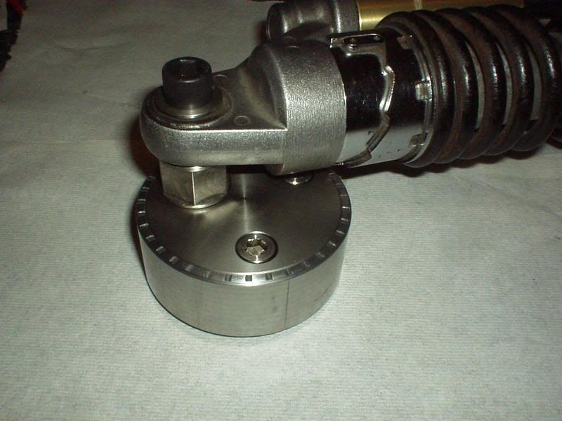
Ooohh think I might just 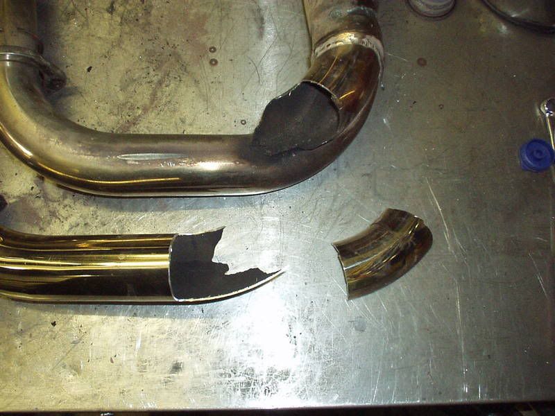 sick  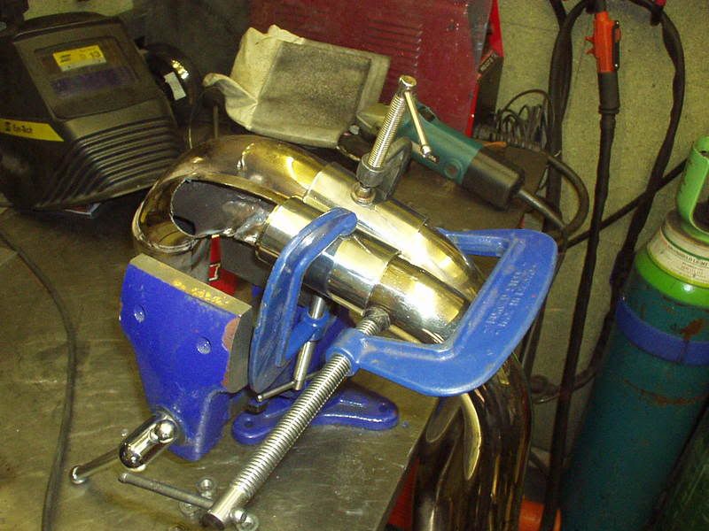 Bit of bracing & internal surgery & finished bar a re polish. 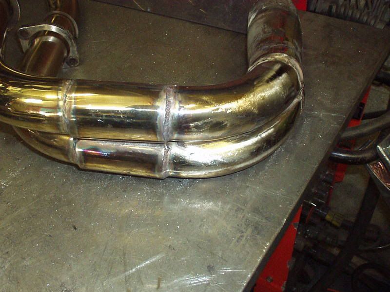 So glad to have got that out my system, back to proper bikes Oft quoted sprockets sizes when going 530 being 17T front & 48T or there abouts out back. Would strongly advice that you get the sprockets & do this test before fixing your new rear suspension mounts. Doesn't matter if you haven't got an angle gauge as the limit is how much chain you mind having on the arm. Research I've done is that 12 deg swingarm angle good as a basis to start with & try to stay within 10-13 deg. This pics shows that 11deg is about my limit (of course once I'm sitting on the bike the suspension will sag but I'd like to be able to push it around without the chain dragging too much on the arm & there isn't a swingarm protector block/rubber being used in this setup). Also chain runs close to the bottom brace. 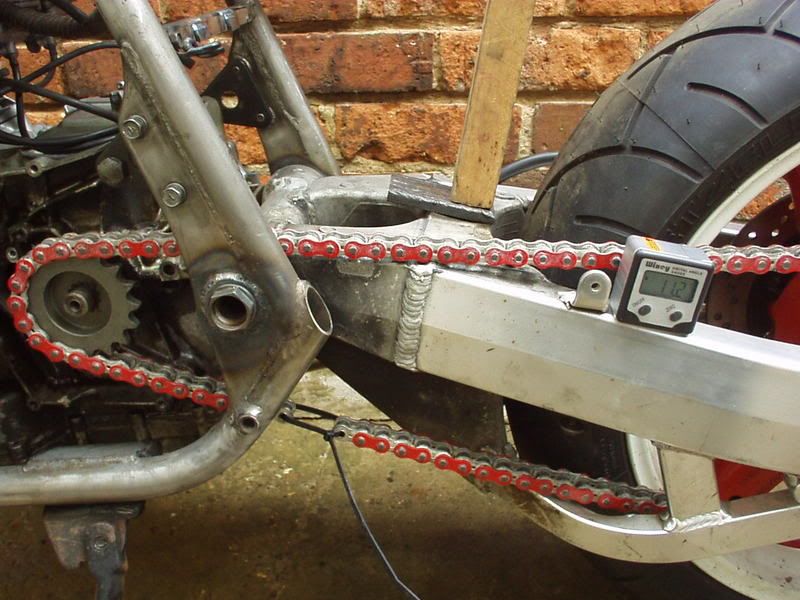 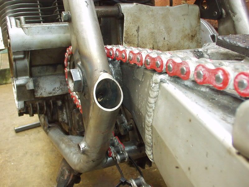 The TLR arm kicks out more to the left & as I will be using twin shock I need to measure the offset on both sides so that I can design the top & bottom shock mounts. There is 12mm difference in the measurement between the left & right sides when measured from the inner swingarm face to the outside of the top tubes. 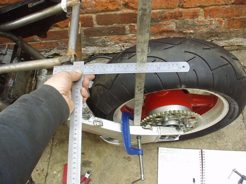 Current mad idea is to have concentric adjustable top shop mounts (similar to the wheel spindle adjusment on some JMC/Metmachex swingarms). This cutting disc is the size I want to use, which matches the curve on the bottom of the side panel. The shock & mount would be on the 'inside' so the side panel would cover it. 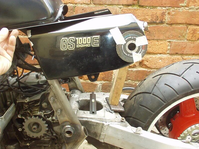 A lot of people using 'lay down' shocks as developed by the Yoshi race bikes, have a spec sheet which shows that one model had a shock angle of 54.5 deg. Replicating that I can mark a top mount on the cutting disc & also a bottom mount on the swingarm. 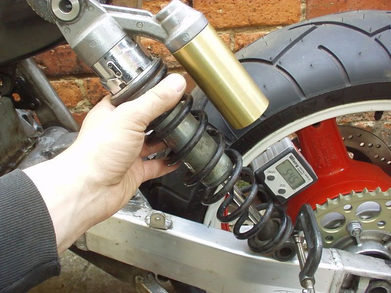 The next thing I did was take lots of measurements & I'm going to use Tony Foales Motorcycle Setup software to simulate this mock up & try to understand what it's all about. |
|
|
|
Post by captain chaos on Aug 7, 2013 17:35:19 GMT
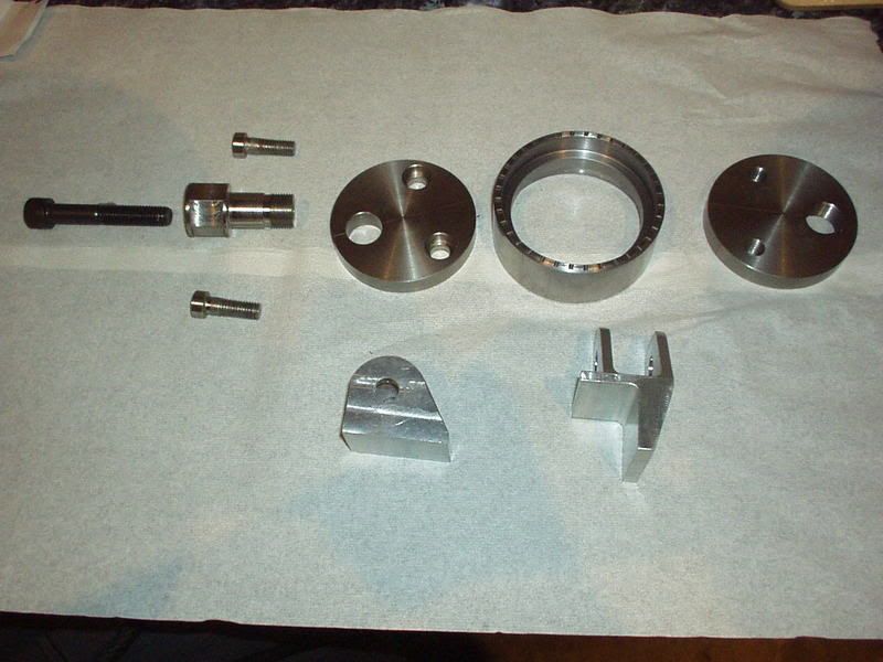
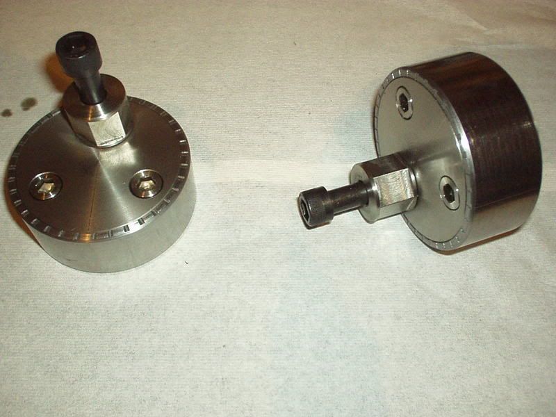
this is the bit that seems to take the time, mock it up, have a look, change it a bit, measure, stand back, change a bit more, stand back, more measurements, etc.... Your not wrong, spent hours yesterday getting to grips with the theory behind angled shocks, etc & I have a better understanding. Need to do a few sketches & then I'll post them up on here as it really does take some of the mystery out of it. On the basis that I have Tony Foales latest book & his software I emailed him a few questions & to his credit he actually took the time to reply, wow what a top bloke Speaking of things that take time, the hidden bits of a project, driving miles finding stuff & picking it up. Said earlier that this won't be anywhere near ready for the OSS party as my crank is away & won't be back till after, but intend to bring it along in the pickup & want to get the new subframe tubes in & included with that is the rear suspension mounts. Got Super Larry primed to do me an 'urgent' job & here are most of the materials for the concentric adjustable top mounts & a block of alloy for the lowers. Included the £10 so you can see the scale, the taller section of round is mild steel of which the two outer parts of the top adjusters will be made which I will weld into the frame tubes. They will be the outside diameter shown (90mm) with the middle machined out & each 45mm in length. The four smaller length discs are stainless & will be turned down to 80mm outside diameter 10mm in length to fit inside the mild steel outers (as per the same principle chain adjusters on some JMC/Metmachex swingarms). The four stainless bolts are to clamp the the stainless inners together (so the top suspension setting doesn't rotate once selected) & the remaining two bolts are high tensile steel which will be used to bolt through the shock eye. What's missing is the material for the 'stubs' either side that the shocks eyes will bolt to. Had trouble getting suitable material but know what I'm after now. 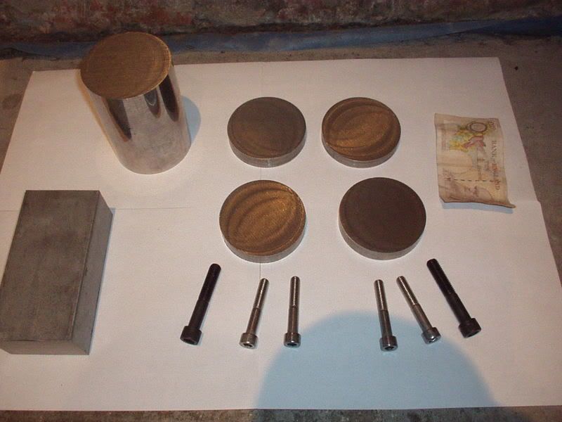 More time & money, parts arriving. Been waiting for the Pingle fuel tap as playing with the petrol tank position I couldn't finalise it due to the tap being very close to the carb top. Bottom left are some clever bits (supplied Debben Performance) they are part of a Dzuz fastner setup that you can weld to your frame. The GS sidepanels have a bottom tab which sticks out below the bottom line of the panel, thought about cutting it off & plastic welding it 180 deg but the Dzuz fastner is so much better. I can mount the other part in the bottom lip of the side panel where it won't even be seen. Other parts include two 17T 530 front sprockets which will be chopped around to form an offset sprocket / out rigger combo. Steering head bearings & wheel bearings as most handling probs are due to wear so good to start out fresh. 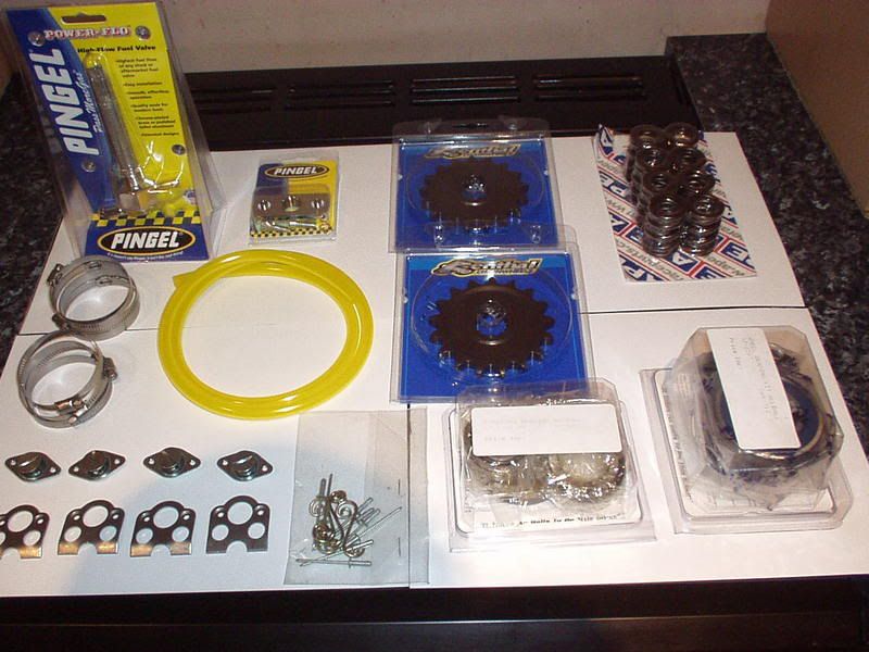 Running around like an idiot on Saturday but have all day on Sunday to start some frame bracing |
|
|
|
Post by captain chaos on Aug 7, 2013 17:37:25 GMT
My head hurts  Was up till 2am this morn finalising the design & doing the drawings for the top & bottom shock mountings. Got a bit complicated as the chain side of the swingarm kicks out more than the brake side but I wanted the shocks to be set out the same distance from the frame tubes / rear tyre on both sides meaning the right hand bottom shock mount is offset more on the arm. Went to see Super Larry this afternoon & I hope to have all the parts back Tue eve or Wed eve at the latest. First job then will be to go & see the alloy welder to get the new bottom mounts welded in place on the TLR arm & then I can get stuck into the new subframe tubes / top mounts. Only gives me Thur / Fri morn to get that done prior to bringing it up to the party Sat morn All part of the fun |
|
|
|
Post by captain chaos on Aug 7, 2013 17:40:22 GMT
Slow progress last few days, great plans to do a bit of small bore tubular bracing at the front of the frame so need to carry on with paint stripping the frame first (I'm clear coating the frame & don't want a blasted finish). Under what paint was left is loads of rust  lots & lots of rubbing down to do before I can even think about bracing this bit. 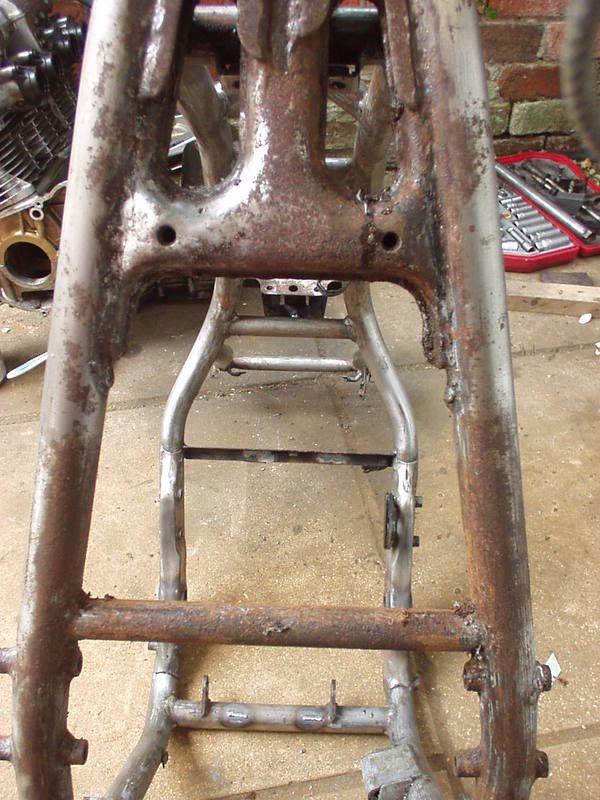 Cleaned up a bit of work I did last week, this is the tank sitting nicely almost on the front down tubes. There is normally a great big bit of mig weld in the way (attatched to a bit of frame tube  ) but have been re working things a bit 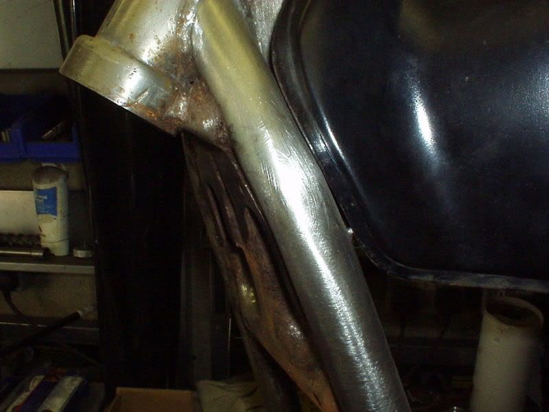 Started on the frame cut outs similar to what I did on Stevea's Kat, this is the messy looking part. As I'm use 1/4 tube for the curved ends I do the top & bottom cuts & then (in this case) the tube I shall use is 25mm diameter so I half that measurement & make a further cut in the area to be removed 12.5mm away from the top & bottom limits. That prob didn't makes sense but will do in later posts / pics. 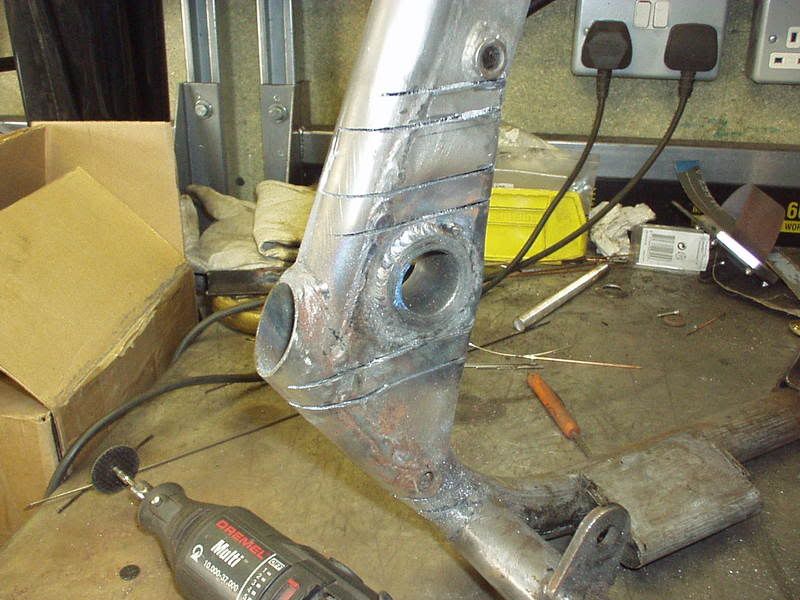 Been doing a lot of this as well, not a lot of room in Strangeland at the moment so keep having to put everything away in the w'shop when finished & take it all back out to do / get to anything 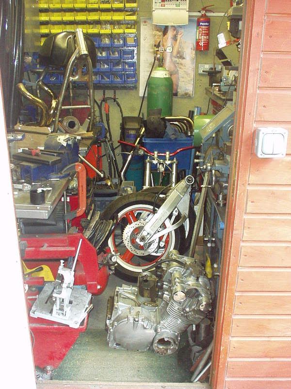 |
|
|
|
Post by captain chaos on Aug 7, 2013 17:42:00 GMT
Carrying on with the chain cut outs I started above this is them very rough cut. 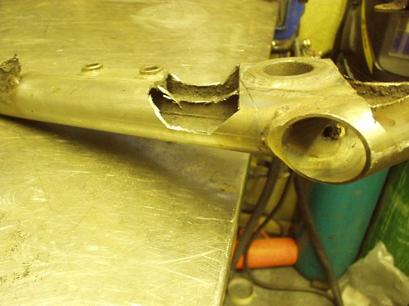 Need to do a quick mock up setting the arm at the max angle I found I could run earlier. 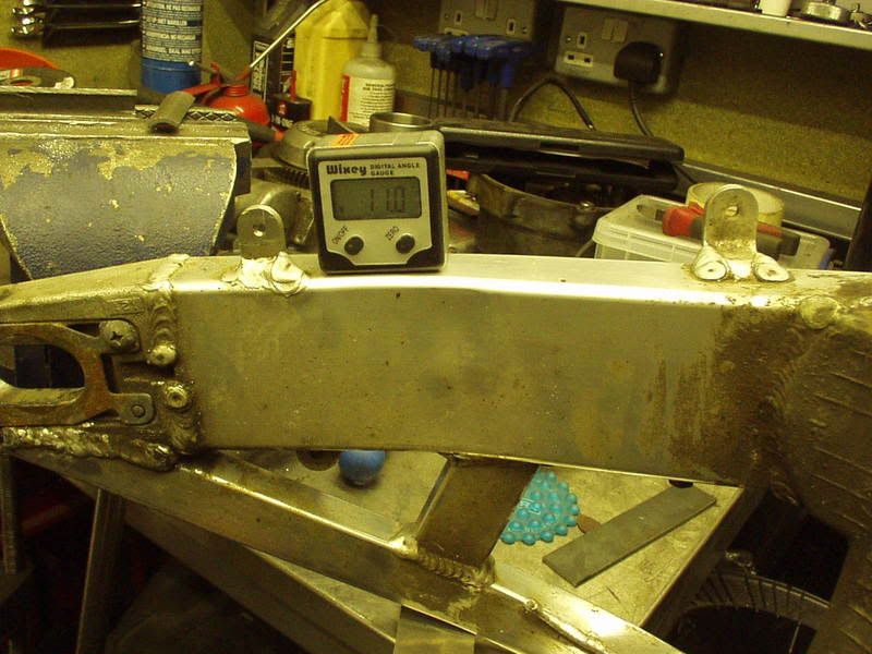 When I did Stevea's I had to redo the top & take a bit more out, thinking about the reasons why I'm sure one is that I set the frame tubes flat on the bench when I did the working out. This time I've set mine at 6 deg which is the angle I measured earlier when it was a rolling chassis. 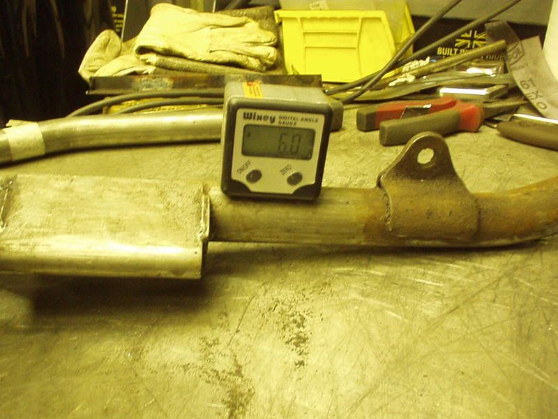 Swingarm in, this is what I've got, need to get a bit more above the pivot as I'm using 3mm plate & tube wall thickness to build it back up. 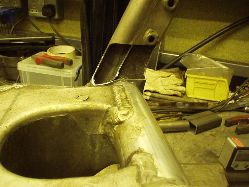 From the rear. 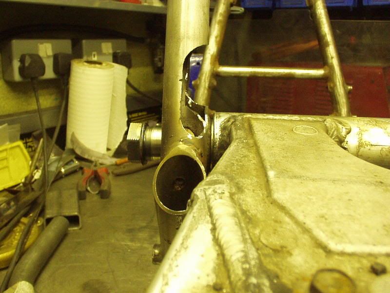 Good shot of the new swingarm bush I fitted, you can see to get them in place there is quite a bit of structure to drill through.  To gain a bit more I'm going to drop the 1/4 section of tube just inside the frame edge but to do so needed to drop the side curve lower to create a lip. 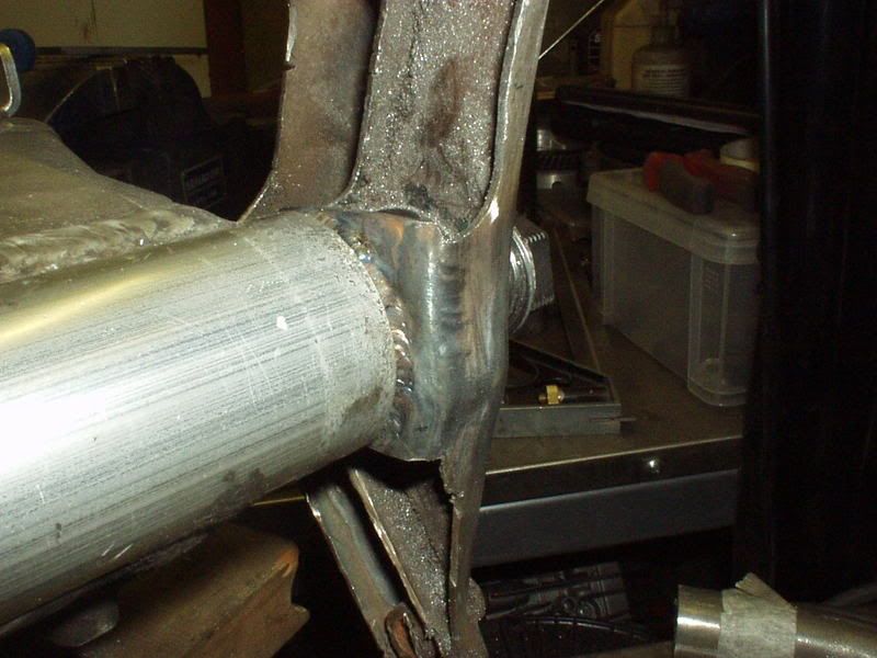 1/4 section of tube. 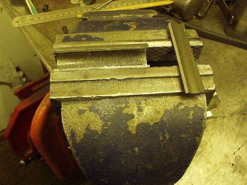 Cut & front section in place, the rear section slopes down at a sharper angle & is done separately. ![]() i73.photobucket.com/albums/i209/Strangewayz666/01Jul08inplace.jpg i73.photobucket.com/albums/i209/Strangewayz666/01Jul08inplace.jpg[/IMG] Ready to weld, I'm using the parts from my Swingarm Bush Jig threaded onto the spindle & then clamped up to resist movement. 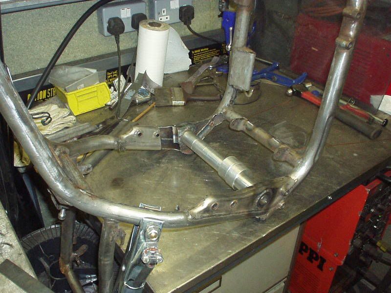 |
|
|
|
Post by captain chaos on Aug 7, 2013 17:43:11 GMT
You're getting a bit good at this now mate...........Praps you need to relocate to a large shed with some living accomodation and a big yard for the doby!!!! In my dreams maybe This evening went to see how Super Larry was getting on making the rear suspension parts I drew up. All I can say is wow he's certainly doing his stuff  . If I can do my bit with the new subframe tubes incorporating the concentric adj top shock mounts to as higher standard it will all look a bit special. Easy to fuck up though as a lot of thought will be needed to get it to work with the side panels but if it does... Hope to collect all the bits tomorrow eve as have the alloy welder primed for Thur morn to weld the new alloy bottom mounts onto the TLR arm. Right back off to the w'shop to do a bit more on the chain cut outs. |
|
|
|
Post by captain chaos on Aug 7, 2013 17:44:22 GMT
Got these pieces of the jigsaw in welded & filed smooth last night & then this morning... PeteG hijacked me to do a bit of work for him. He still has a chance of finishing & riding his bike to the party & I had said if that was the case I'd stop what I was doing to help him out. Oh arse bollocks. 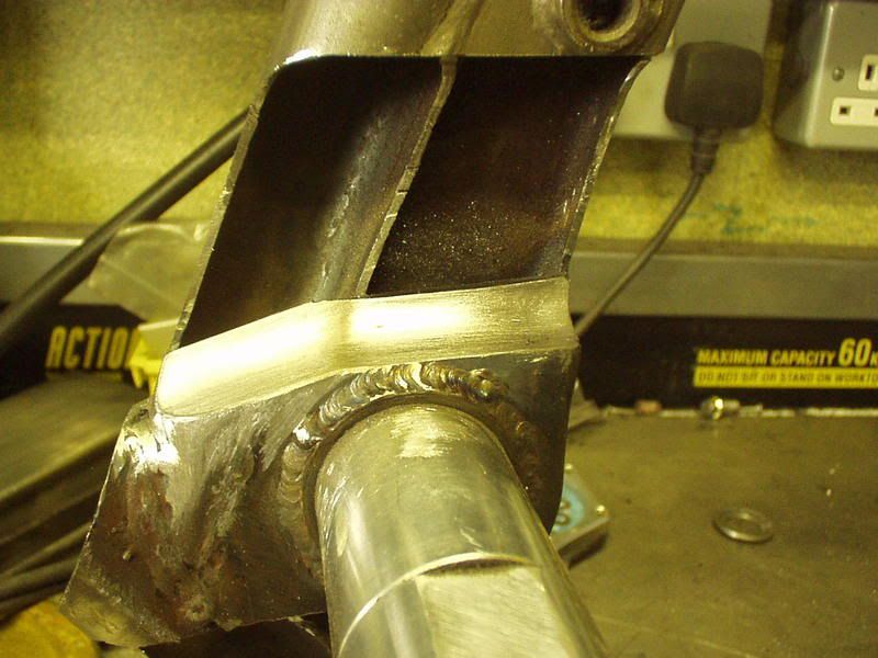 |
|
|
|
Post by captain chaos on Aug 7, 2013 17:45:52 GMT
|
|
|
|
Post by captain chaos on Aug 7, 2013 17:47:00 GMT
For Facks sake it's supposed to be July, get up early shite loads to do today & its pissing down, how you supposed to work in this. Bloody place  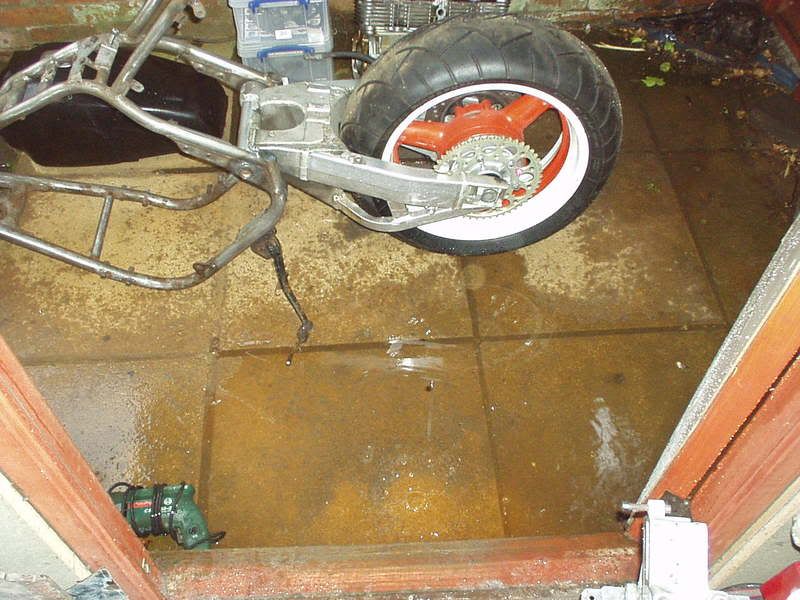 Even got the awning out, guess that makes it a posh shed 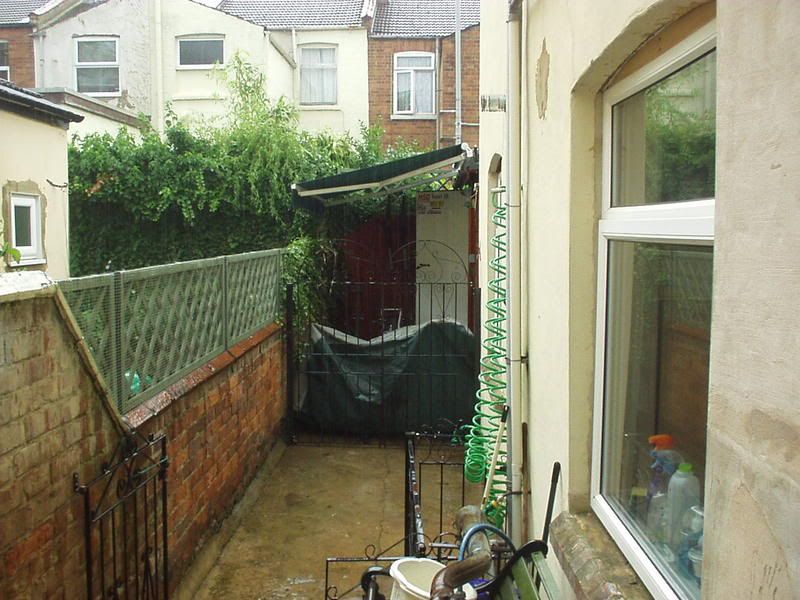 Hope this makes you appreciate your garages more Even the dogs got more sense than to be outside  |
|
|
|
Post by captain chaos on Aug 7, 2013 17:49:05 GMT
Sun came out so I picked all my toys up... Todays job now that I had the bits from Super Larry was another mock up & measure to make sure I got the bottom shock mounts in the best place. You'll like these pics Had to cut a few tubes out the way. 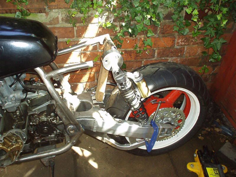 Using a rule from the center of the swingarm pivot & angle finder on the shock body. 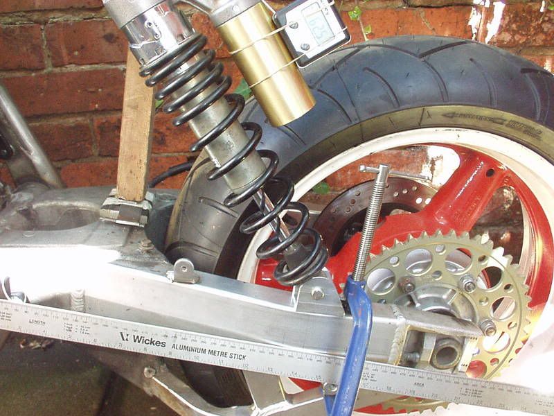 Played around with a few settings drew some charts & with the bottom shock eye 360mm from the swingarm pivot.. 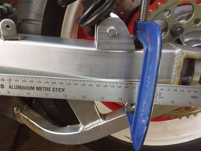 An angle of 62.5 put the shock in the middle of the progressive zone (for my setup) meaning I can alter the height & angle without going outside that. 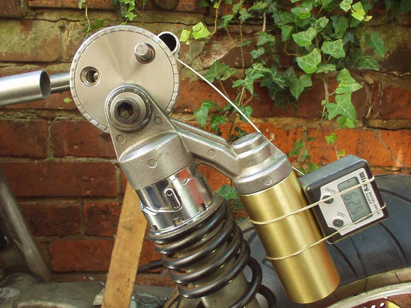 Lots to work out as getting the tank in the position I wanted the side panels had to 'flow' with that & also the bottom right hand corner of the panel needed to hide the top shock mount. 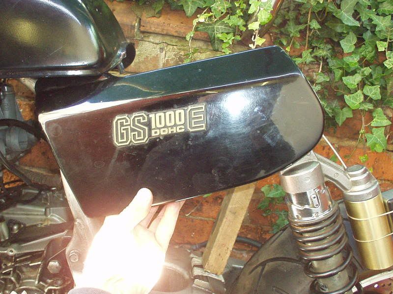 Moving the camera to the right you can just see the adjuster & matching radius.  That done have taken swingarm to the alloy welder & will pick up later this eve |
|
|
|
Post by captain chaos on Aug 7, 2013 17:51:14 GMT
Picked the swingarm up from the alloy welders last night, with the bottom shock mounts now on it was time to see if I'd managed to get the shocks equi distant from the tyre either side (the TLR arm kicks out more to the chain side). Ran into a few problems as measuring from the middle of the shock damper rod to the tyre edge makes the chain side shock what looks to be 12mm further away from the tyre than the right hand side. Think my mistake was that originally I was going to keep the existing subframe top tubes & took measurements from them to set the shocks out. I've since decided to cut them off & put new tubes in higher up, still shouldn't have been a prob with the measurements. Think it's a combination of the existing tubes not being central (ie the subframe is slightly to one side) & the inaccuraces of trying to accurately measure the offset from the outside of the subframe top tubes to the inside faces of the swingarm. BUT it's not that simple, with part of the chain cutouts done it was my first chance to see what the chain run was going to look like. Sprocket will need spacing outwards as the chain hits the tyre. With there being a 10mm gap from the existing position of the chain & the shock spring I do have room to move the sprocket over but that would only mean I could move the shock mount inboard a couple of mm in trying to get the shocks equi distant & this was the side that was 12mm further out. 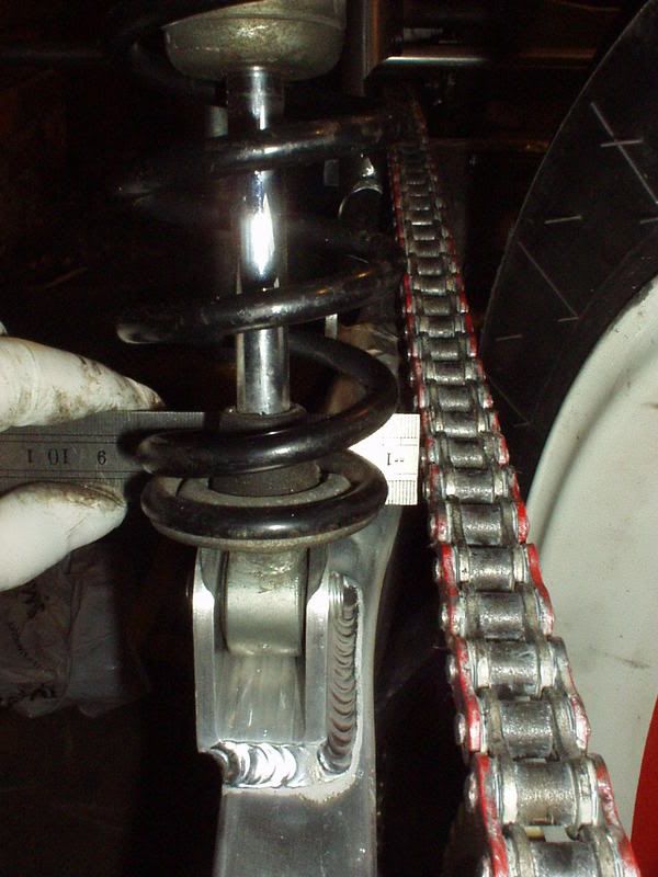 Looking at the other side I'd designed the shock mount to offset the shock a lot anyway & I wouldn't want to have the center line of the shock (force) any further out than it is (center line right on edge of arm). 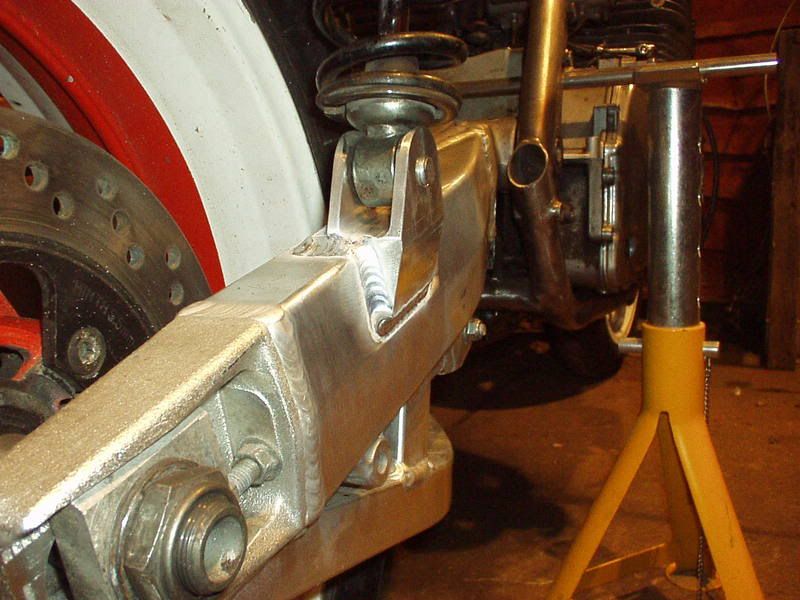 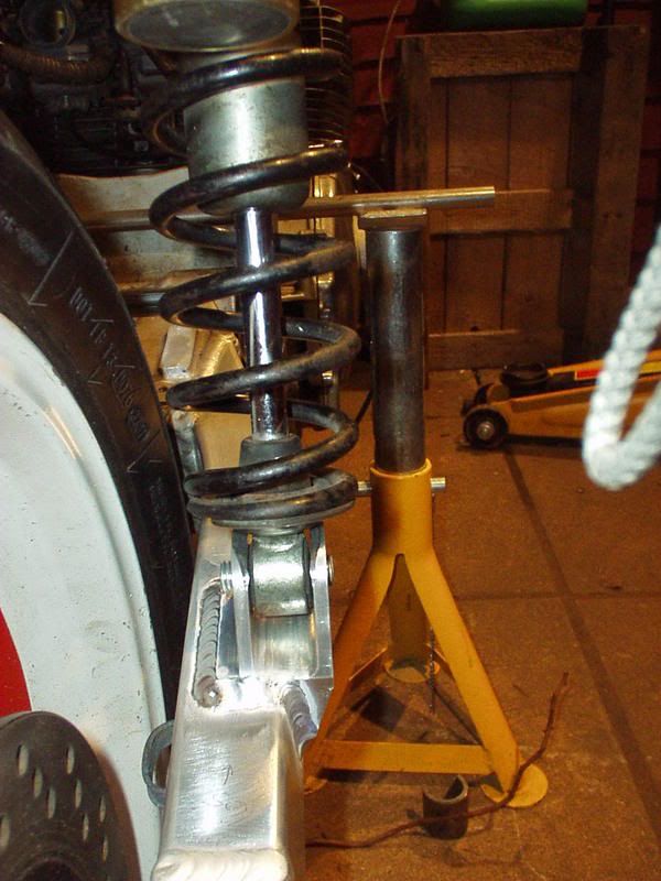 So even though my measuring had failed to get the shocks equi distant I'd done enough 'good work' to actually get the shocks in what are the best postions for each side. I could move the left further in a bit (but it's not worth cutting the mount off & trying to reuse it to gain 2mm) & the right hand side I wouldn't want to move further out. As part of all this I wanted to check the obvious that the wheel was central, it should be as using the arms exsiting spacers. When I did Stevea's Kat I had Super Larry make me a top tube level to assist in the 'string down the top tube' method. I'd set the bike up on a bar supported by axle stands with the swingarm pivot level first. 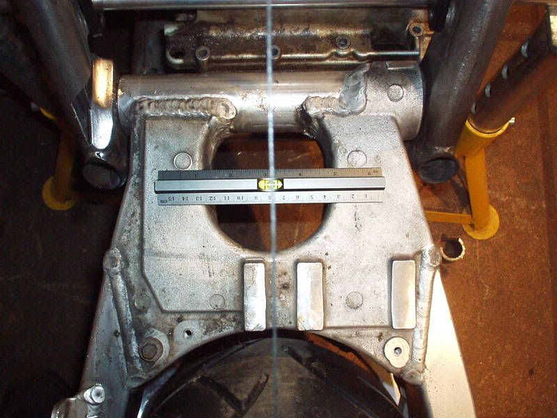 Then using the top tube level ran the string along the tube & onto the tyre. 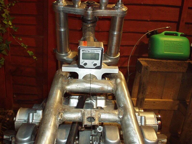 Still difficult to do on your own but I'm happy enough that the wheel is central. Need to get Super to make a new offset stub for the left hand top shock mount, as I had both stubs made the same (assuming the shocks would be equi distant). If I used the one I have the left hand top adjuster would (like the shock) be 12mm too far offset left, as would any new subframe tubes on that side, making the bodywork all pissed as well By getting a new offset stub with 12mm extra in it I can move the left hand top adjuster inboard to get the top adjusters spaced correctly whilst keeping the actual shock in the postion it is now. This pic shows that the left hand top adj is too far out. 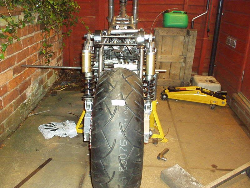 If you thought reading that was hard work you should have been me at midnight trying to figure it all out ;D Still made time to take pics though |
|
|
|
Post by captain chaos on Aug 7, 2013 17:52:57 GMT
Got serious this morning, off came all the existing subframe tubes, needed to be done but if I can't get enough back in to support a rolling chasis the GrebRod won't be off to the OSS party Sat afternoon. 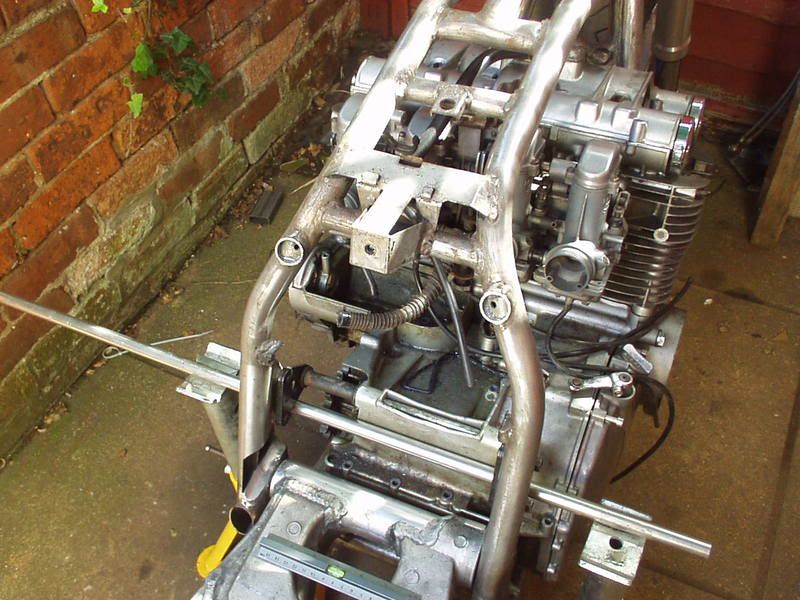 Anyone got some more stuff I can use to prop things up, wood, files, socket extensions bars . You'll be pleased to know that I designed the top shock adjuster plates so I could run threaded bar all the way through them to help with alignment when welding them in place 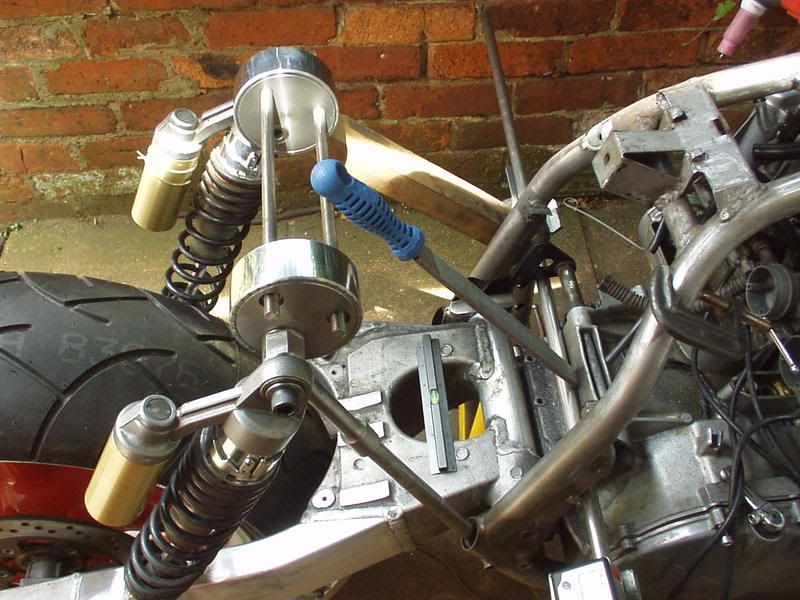 This is tac'd in place, wanted 20deg which is a bit more than tank angle for extra attitude. Pleased to get 19.8 as holding the dam thing in alignment whilst welding it with the other hand was tricky to say the least. 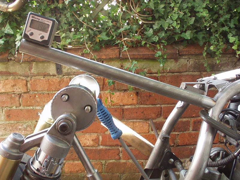 Next I set up the other side, this is what I was going on about earlier re getting a new stub made with an extra 12mm in it. Here it is just wound out that much with the adjuster body moved inboard on the threaded bars 12mm. 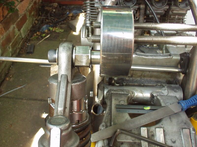 Other sides stub for comparison. 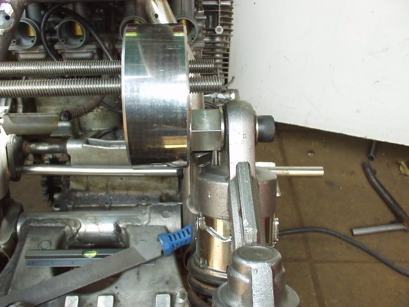 And with that I had to go to bloody work, how pissed off was I Got hme few hrs ago & got the other top tube in & level 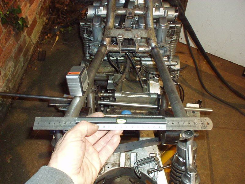 Too late to grind any more tube profiles but I've got about 4hrs in the morning to see if I can get it done, looking unlikely To cheer myself up here's a mock up of what the rear will be looking like, shite picture (Mrs Strangewayz was directing :  . I'm going to cut & shut the stock GS tail piece so its angle to a point at the back & use this LED GSXR light. Looks the bollocks in the flesh & has some serious 'air' with the stance. Idea at the moment is to have a number plate all on one line (metal pressed) & put a ring through both top corners & hang it from a cpl of little brackets off the the bottom of the top shock adj bodies, so it just swings like a house sign  I've never seen that done before. 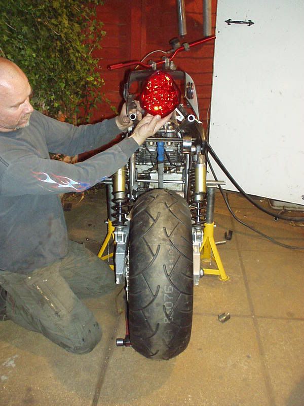 |
|


 When I was free it bloody rained so couldn't carry on with what I needed to outside. Gave up & started to fix the Buell (weld up the bloody exhaust). Should be back on GrebRod Wed & then mad on it up till the OSS party.
 Talk about make yourself at home

 lots & lots of rubbing down to do before I can even think about bracing this bit.
 ) but have been re working things a bit
  .
.


 .
.