|
|
Post by captain chaos on Aug 7, 2013 19:09:35 GMT
come on m8.... either you're really busy and about to shower us with kwazilions of photos or you've bailed on us  ... and i know that wouldn't have happened, whileads to .... WHERE YA BEEN?  Guess I shouldn't complain, advertised my 'spare' car late Sunday expecting it to take at least a week to sell, started back on GrebRod Mon, sold the car Tue with it being picked up Wed but it did involve me doing a few jobs & turning the house upside down hunting out all the spares & service history for it. Lost two mornings but bank balance looks better  So at last back on GrebRod this morn |
|
|
|
Post by captain chaos on Aug 7, 2013 19:11:36 GMT
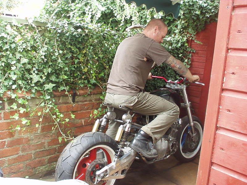
Whilst I've been off the pace with the fab recently have kept things ticking over (in my head ). As I'm trying to keep a proper Old Skool vibe with some of GrebRod's parts like using the original switchgear I also want to try & use the existing rubber footrests as that fits in with the opposite of cnc bolt on bits for modern bikes that I'm trying to avoid with this project. Existing footrest. 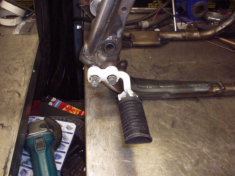 I'm sure this has been done a few thousand times before but instant rearset by turning thru 180 deg. (Look also where the two mounting holes are in the frame). 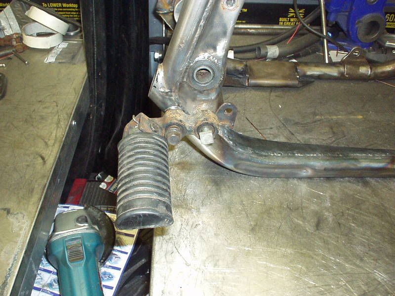 Problem you get & worse in my case is that the mounting holes on the other side are in a different position & I've lost one as it was in the lower subframe tube that I cut off 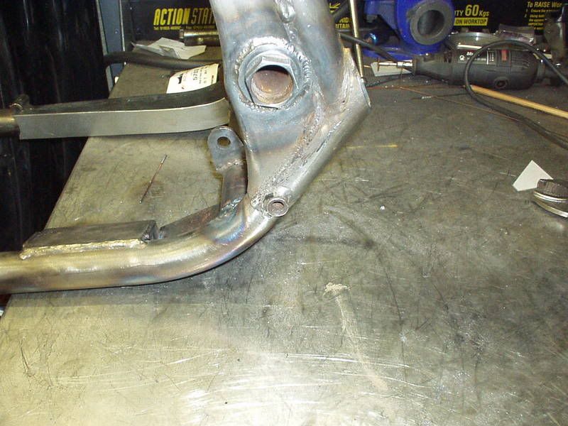 You can see from the footrest themselves that each side is different. 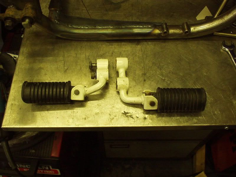 No prob, few weeks go past & the Evil place sorted that, another set of footrests. 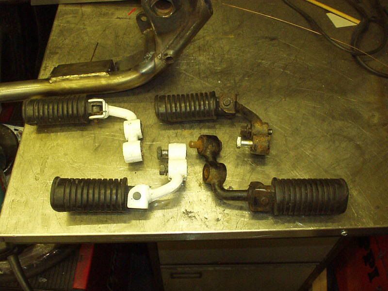 Picked these up from Super Larry Tue eve, threaded sockets so that I can duplicate the mounting points on the side that currently only has one. This had been holding me up a bit as these will go thru the area that I'm doing my chain cutouts & as I brace the frame internally in that area I needed these in place before I can finish the chain cutouts. 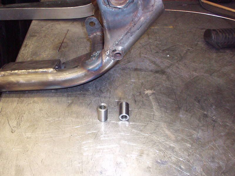 Ok, it's not going to be that straight forward as I'm converting from drum brake to disc brake & am going to have to make up longer parts for the gear shift linkage but in my head it all works. Think also it will be another one of those bits on this bike that most people won't even realise has been heavily modified.. oh look still got the stock footrests on it  Whilst at Super's also picked up this, from earlier I ended up having to offset the chain side top shock mount more than I had originaly calculated, here is the new stub that he made for me. 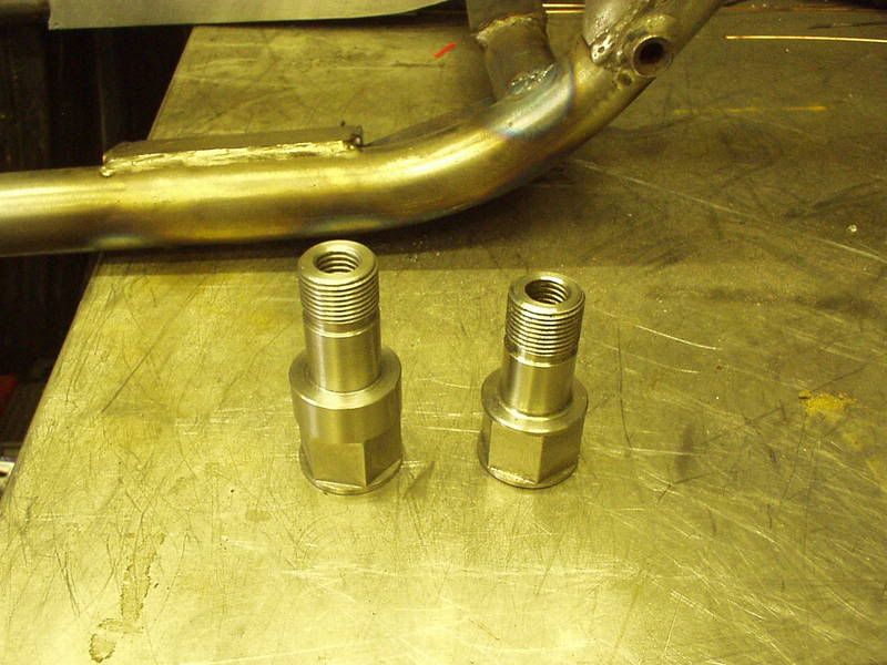 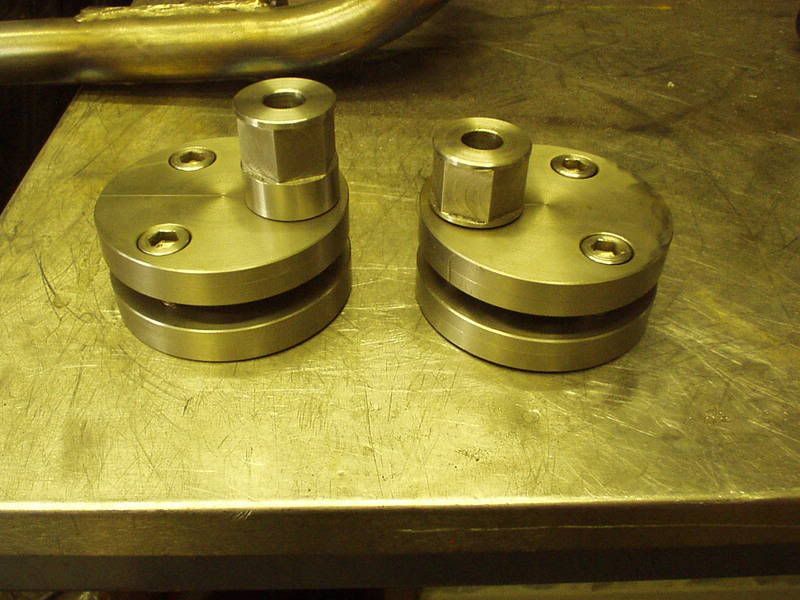 |
|
|
|
Post by captain chaos on Aug 7, 2013 19:12:38 GMT
Bit of fab today, needed to carry on with plating the top of this in. 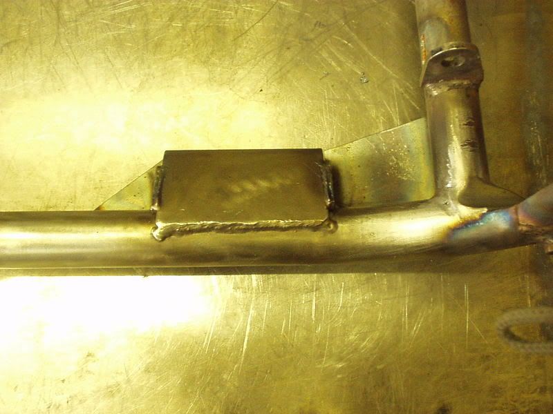 Faffed a bit as was looking at doing curved sides to match the side stand mount part or cutting off the side stand curve & replacing with flat... In the end had to slap myself round the head as a reminder that when the engine is in place this won't be seen Front part cut out. 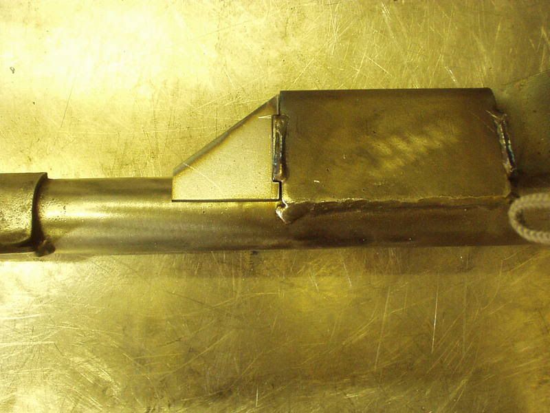 Welded in place you can see the side of this section will be triangular which is why a curved side would be hard to do. By curve you can see where the side stand bracket is bent from one piece of metal forming a curved side. 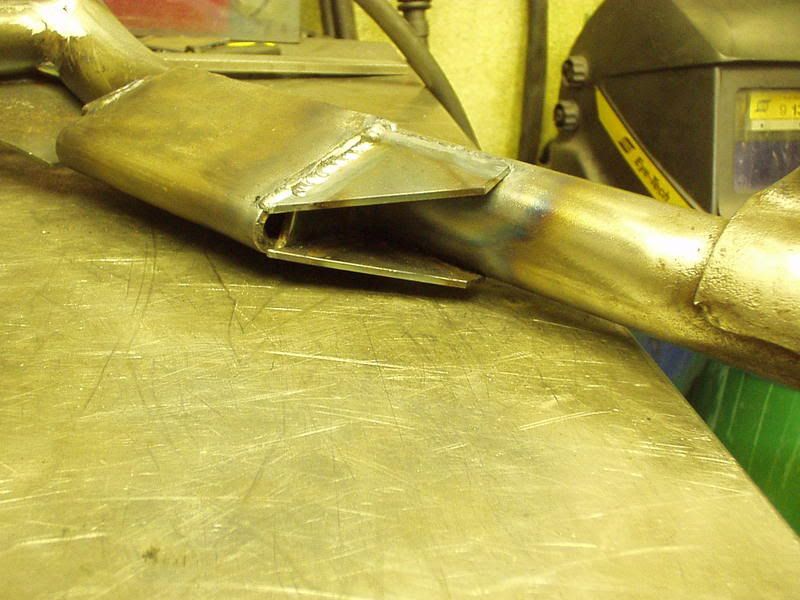 Back part cutout & welded in place. 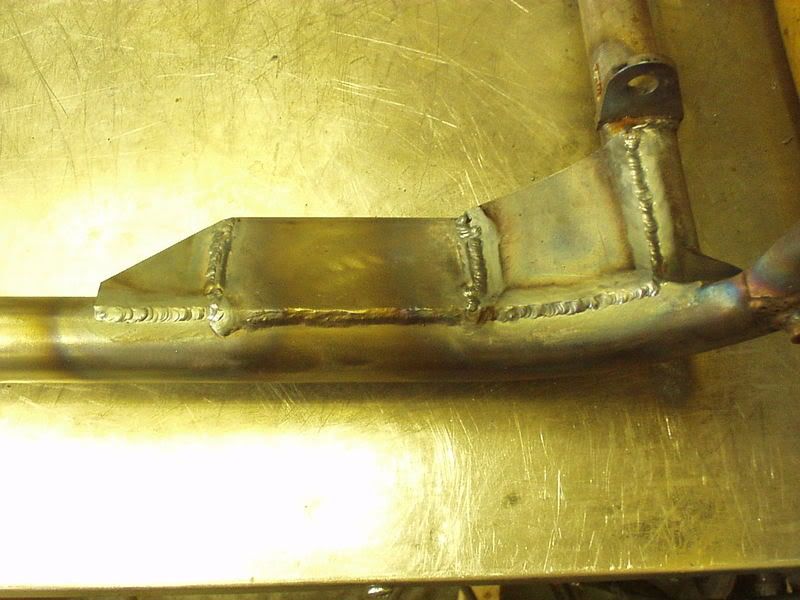 Just the sides to do on this brace now. Bit of a look at why things take a while in Strangeland.. Sides to fabricate. 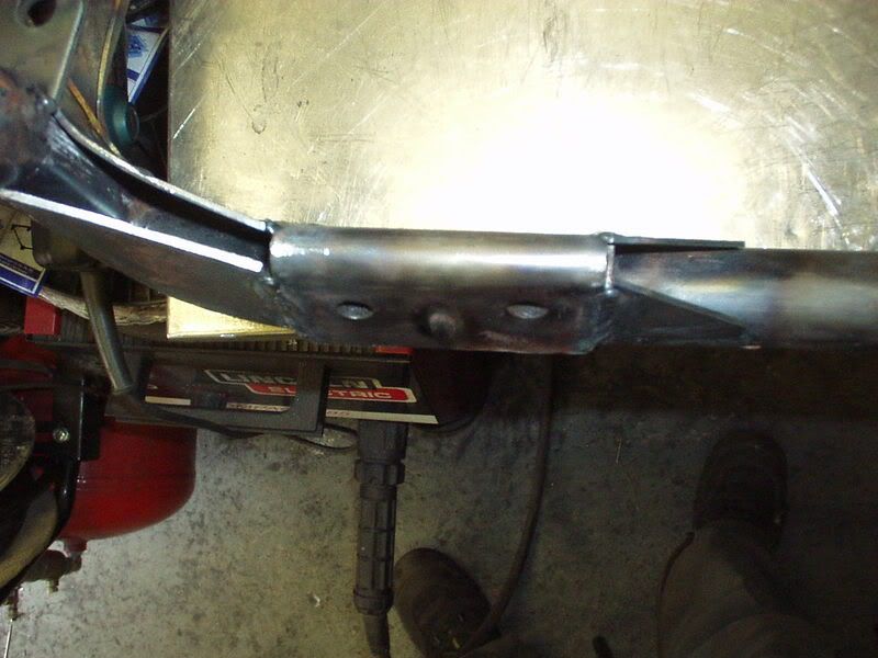 Made something that worked in card first. 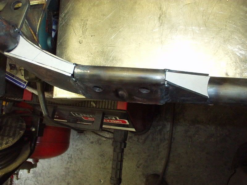 Turned the card into metal. 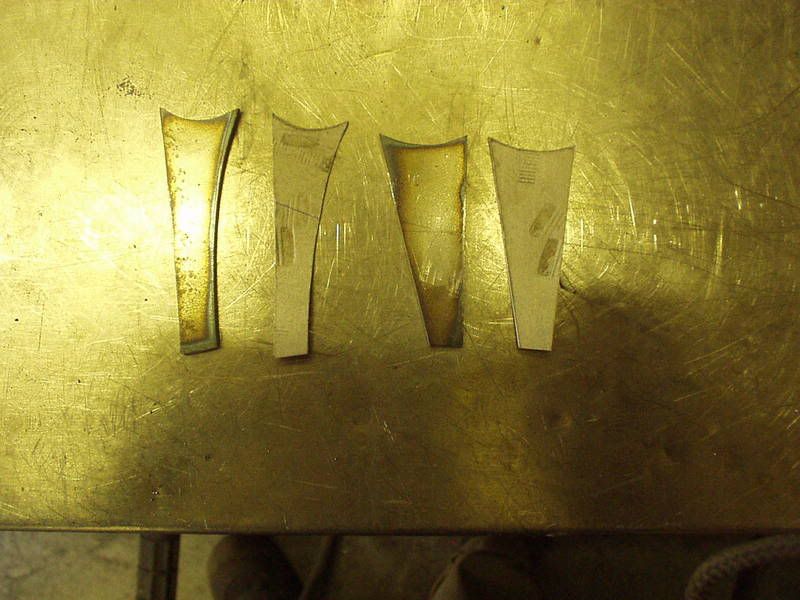 Masking tape works well at holding fiddly bits in place whilst tac welding. 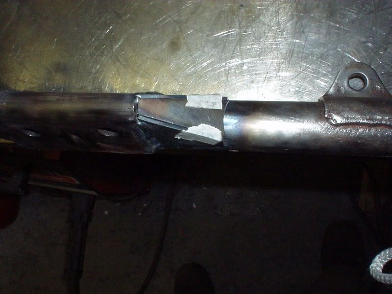 All in, welded & smoothed  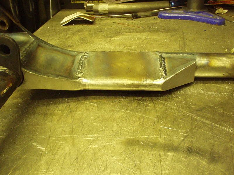 Then I went over to see Super Larry in his proper back street workshop, here on the case making some more bits for me I'm an amateur but this guy is a pro Took the frame over to show him as hadn't seen the top shock mounts he made for me in place & was well into it. 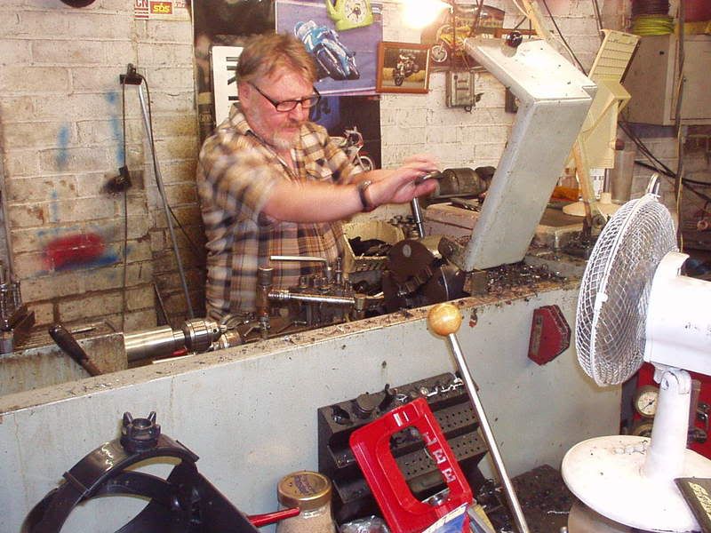 |
|
|
|
Post by captain chaos on Aug 7, 2013 19:16:26 GMT
I think I'm back on it Here's something I've just started looking at, as we all know the devils in the detail & I mentioned earlier I might try this. Getting the profile of the tyre. 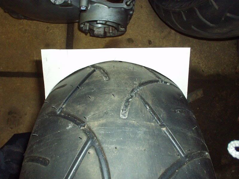 Added a bit in the middle so that it would fit in this space. 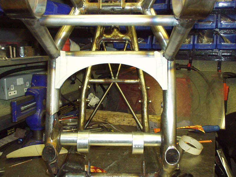 I haven't seen this done before but can't think of a reason why I shouldn't do it, other than extra weight... but as long as I take a good dump before I take it for a thrash that should equal it out Idea being that when looked from behind with the swingarm & wheel in the bracing blends / frames the tyre profile. 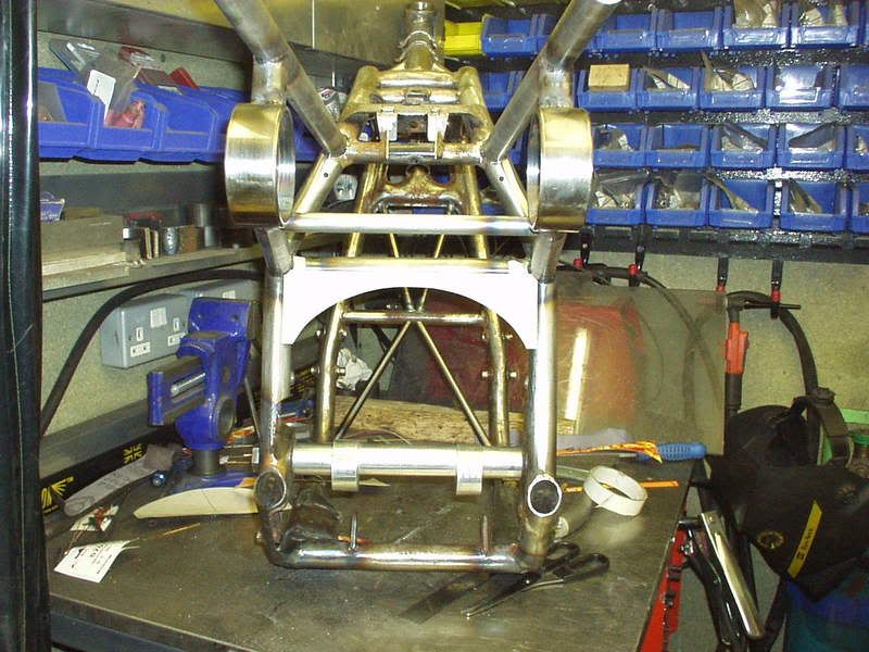 More inspiration needed, which one should I drink first  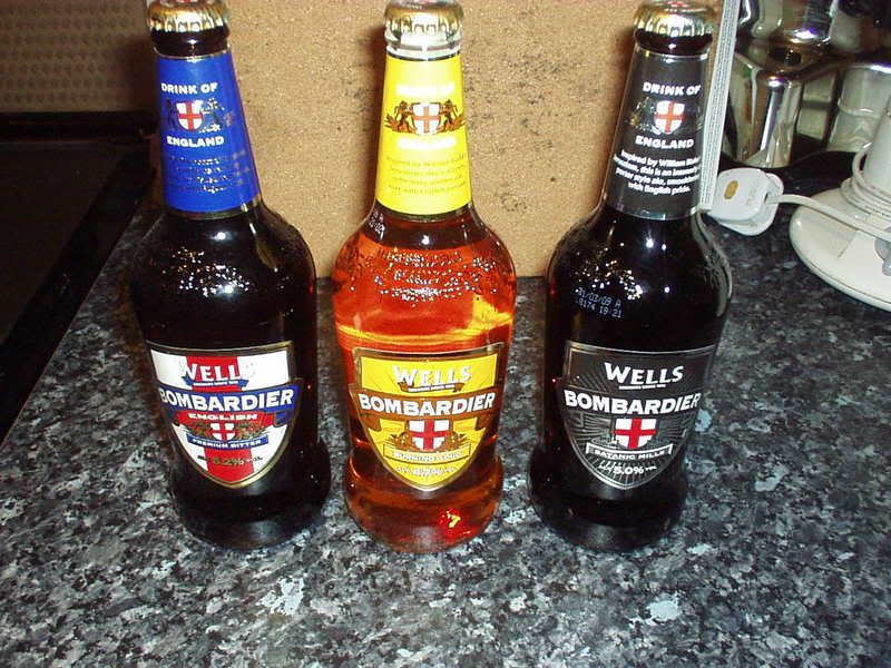 |
|
|
|
Post by captain chaos on Aug 7, 2013 19:18:34 GMT
At a risk of stating the obvious, dont forget to allow for the expansion of the tyre once hot. I know you have anyway, but just incase No worries. I think it was the angle of the picture, there is a better shot below from the side that shows the tyre isn't actually near the brace & it's only when viewed directly from behind that the profile of the tyre & brace will match. Bit more work on this today changing my latest idea into metal, card template & two pieces as it will be a multi sided brace. 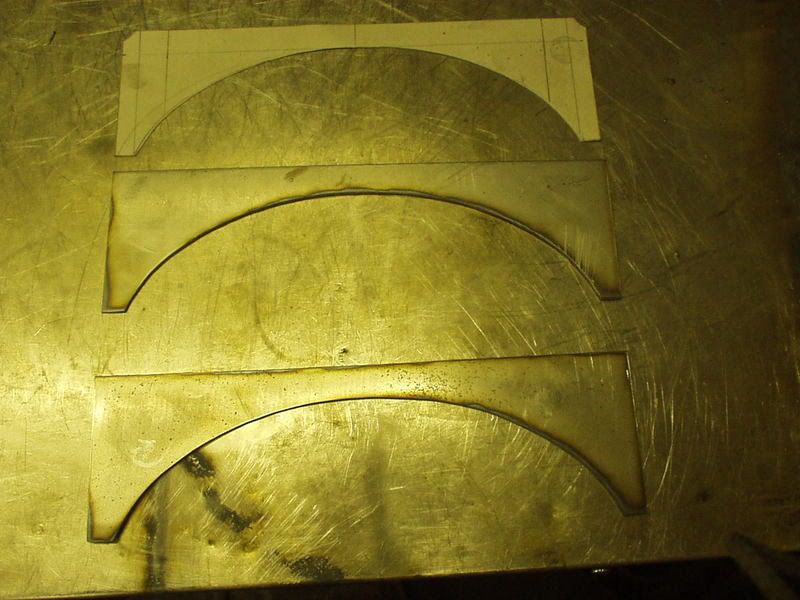 Making it easy for myself & letting gravity hold it in place to tac, have put holes in each corner as I will be welding tubes in, like I did on some of Stevea's Katana bracing (Road to Ruin Project). 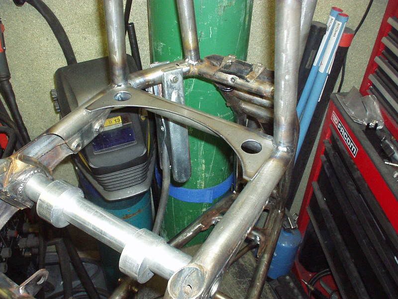 In place 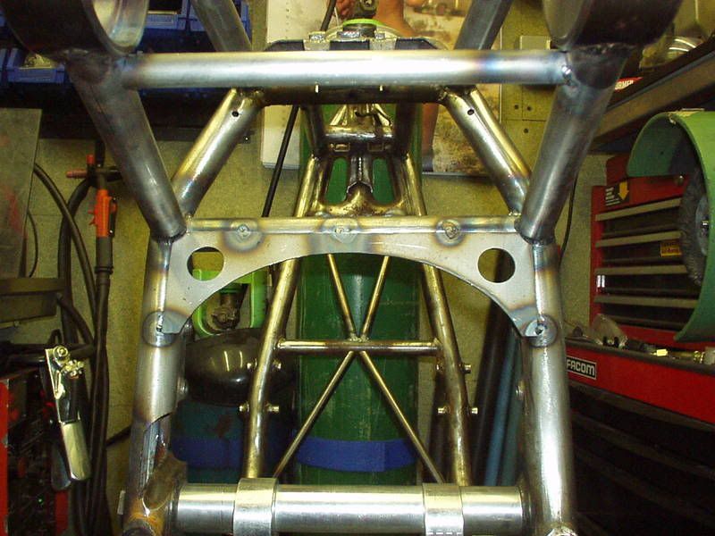 From the side you can see that the tyre won't be anywhere near this, the purpose of the bracing (together with what I have done underneath the engine) is to help prevent the swingarm pivot area moving / deforming as I have removed the lower subframe tubes & half tubed in the area of the chain run. 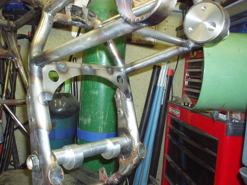 This is the other side which I am in the process of sizing to fit. 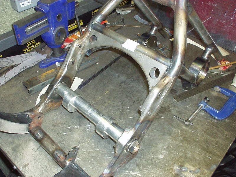 Once in place I will make the curved face. Carrying on from above next job was to cut & weld a cpl of tubes into the plate, found a good way of doing this is to put the tube in a vice (with the top protruding above the top of the vice the thickness of the plate its being welded into) & level the edge with a rule along the side of the vice. 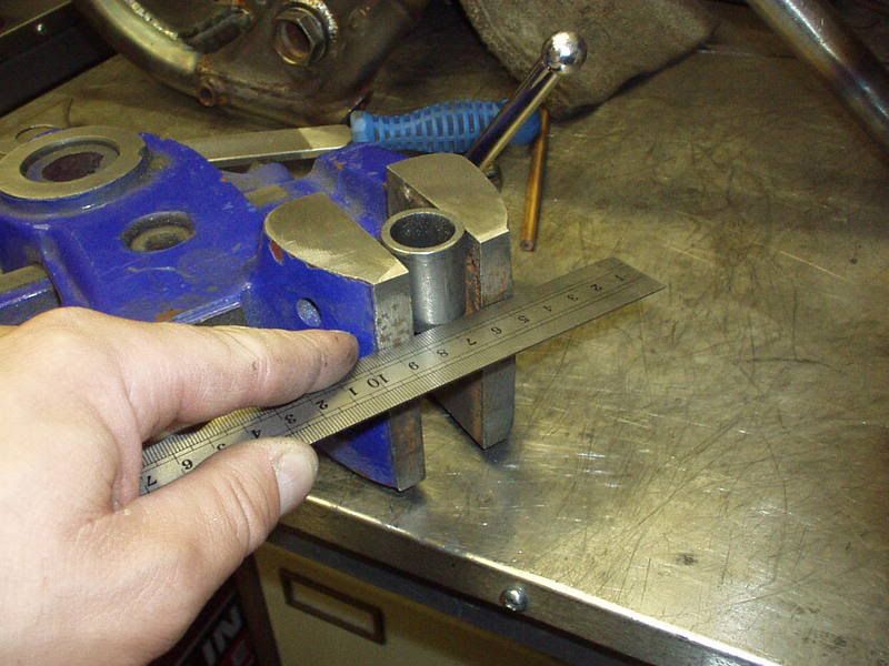 With the tube level put the plate on top. 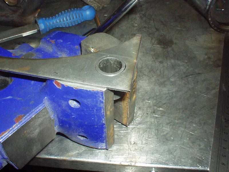 Tac in place. 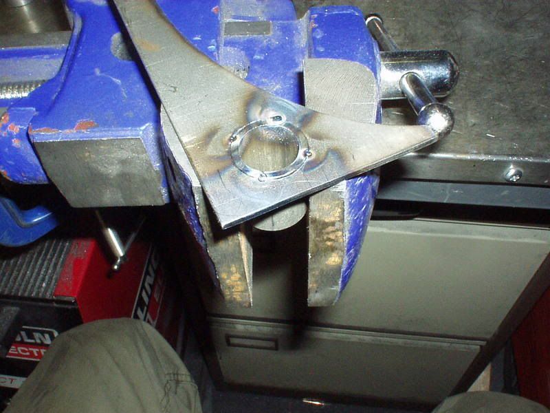 Other side. 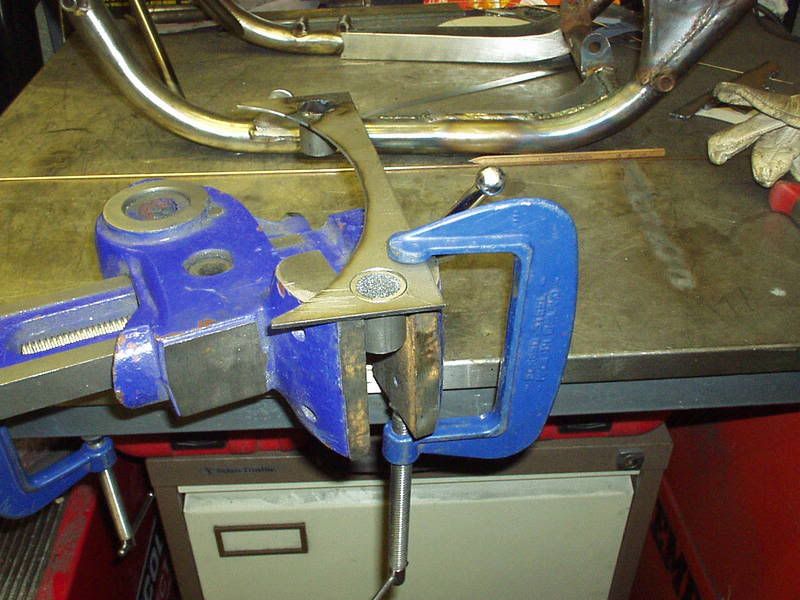 Tac'd it first as I needed to check that I could physically fit this plate in place with the tubes welded or did I have to weld the plate in place & fit the tubes last. It worked so here are both tubes fully welded. 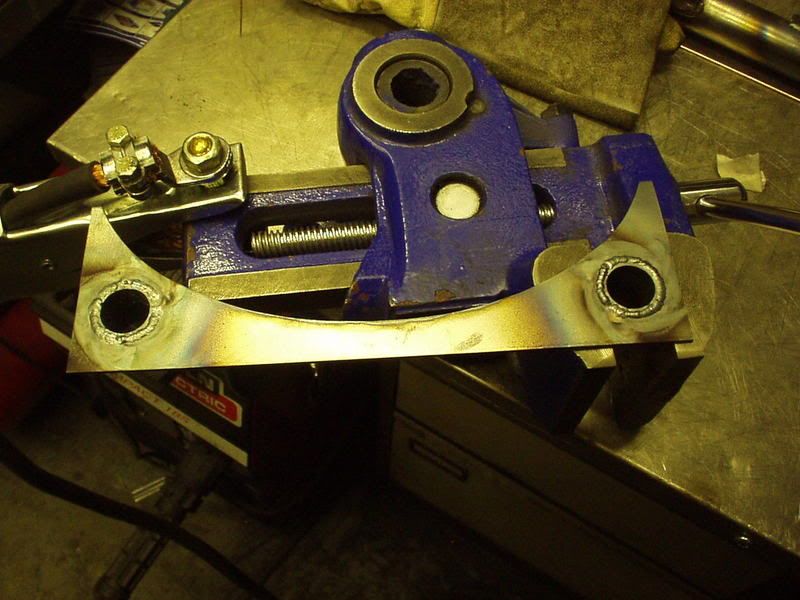 Filed smooth ready to fit. 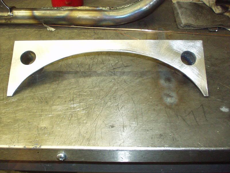 |
|
|
|
Post by captain chaos on Aug 7, 2013 19:22:17 GMT
Fitted the plate in place & tickled the tubes flush with a grinder. 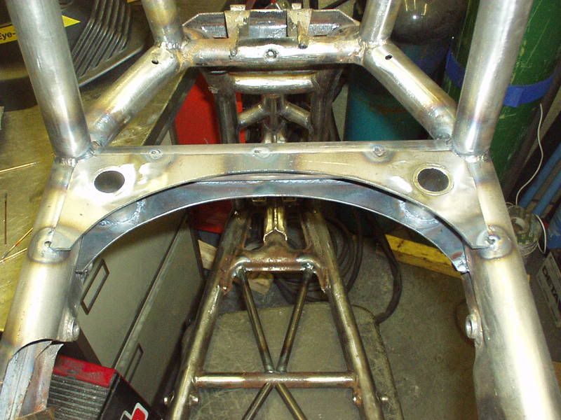 Tubes welded in place. 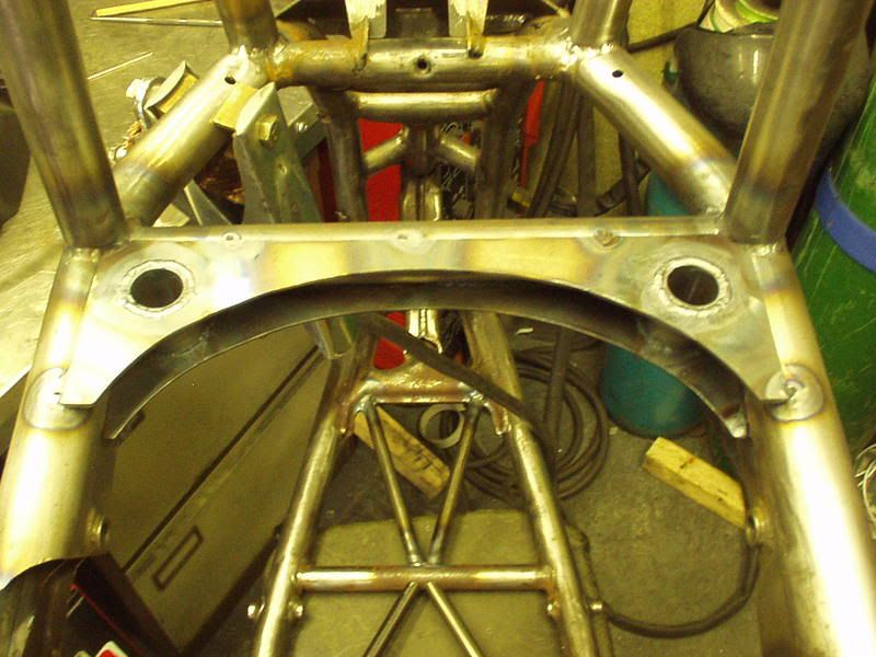 I've filed them smooth & decided to do a mock up as haven't in a while, forgot how brutal it's looking 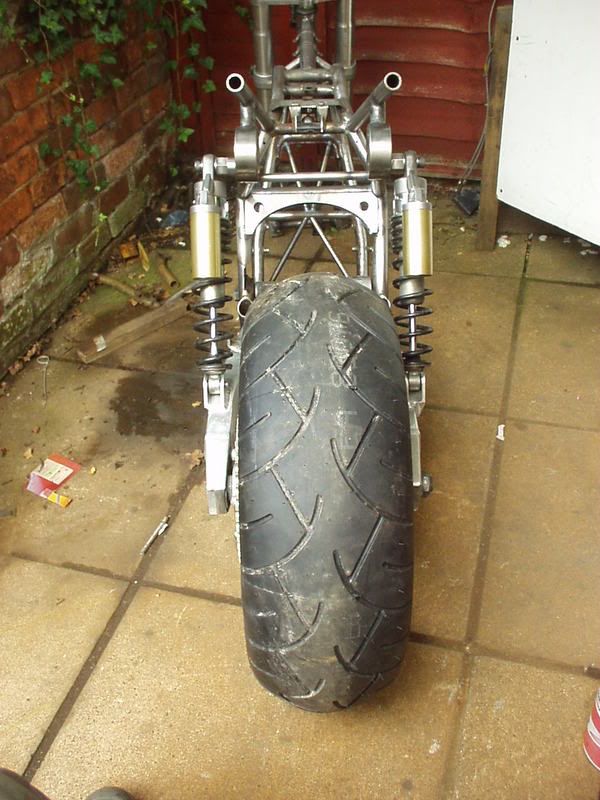 Curved brace almost matches the tyre. 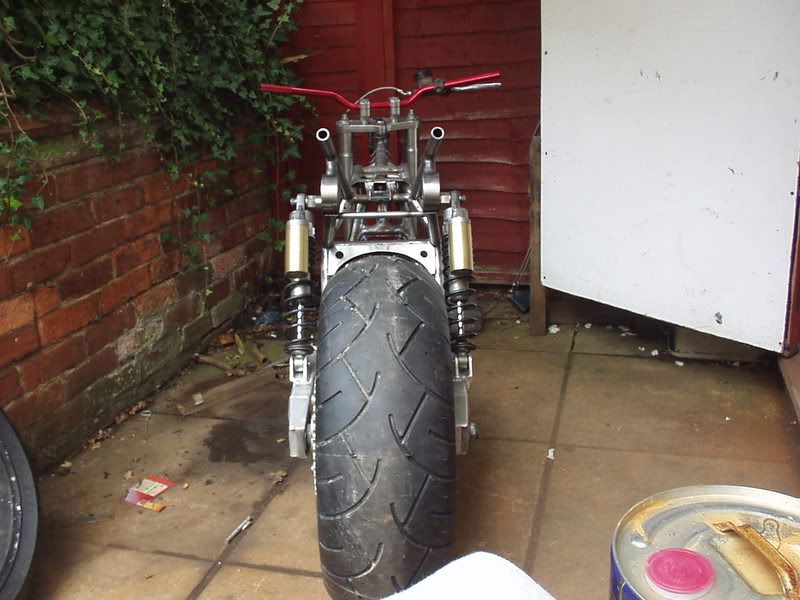 Left side. 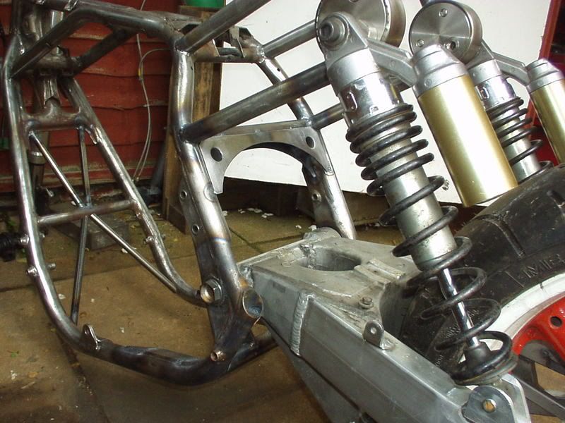 Right side. 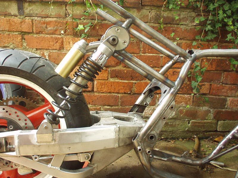 Under engine. 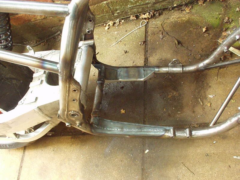 Extended top shock stub that Super made.  |
|
|
|
Post by RICHS202 on Aug 7, 2013 20:12:24 GMT
Chaos, thanks for resurrecting this thread mate. It is pure talent and very inspirational to us all. Nice one.
|
|
|
|
Post by captain chaos on Aug 9, 2013 17:02:14 GMT
Bit of faffing today. Even though I'd been welding everything with the swingarm pivot bolt in & spacers that duplicate the width of the swingarm in place I noticed yestersay when I removed them (to fit the swingarm) it pulled in a bit. Not much, prob 1mm, but enough to be annoying. Think it did that when I welded the curve in for the bottom chain cut out. Using a plumbers propane torch I put a bit of heat in the tubes & then using a bottle jack gave the pivot a little bit of a stretch & then locked if off & left it in place whilst I final welded this plate. Idea being that the heat from the welding would work with the pressure being applied by the bottle jack. 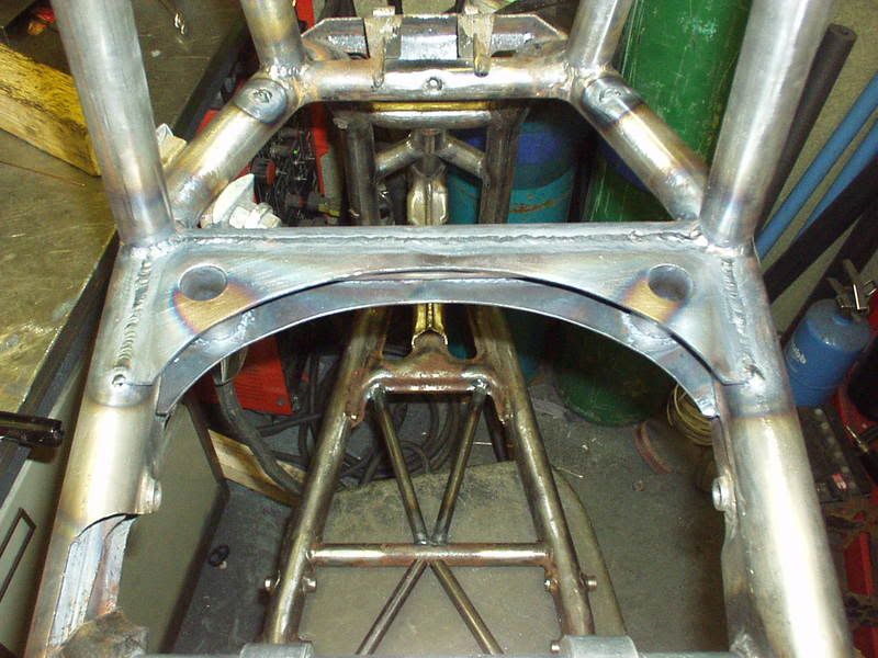 Worked a treat, where as I couldn't (without force) get all the spacers back in before they slip in lovely now With the pivot bolt not tightened up the spacers spin round nicely again . 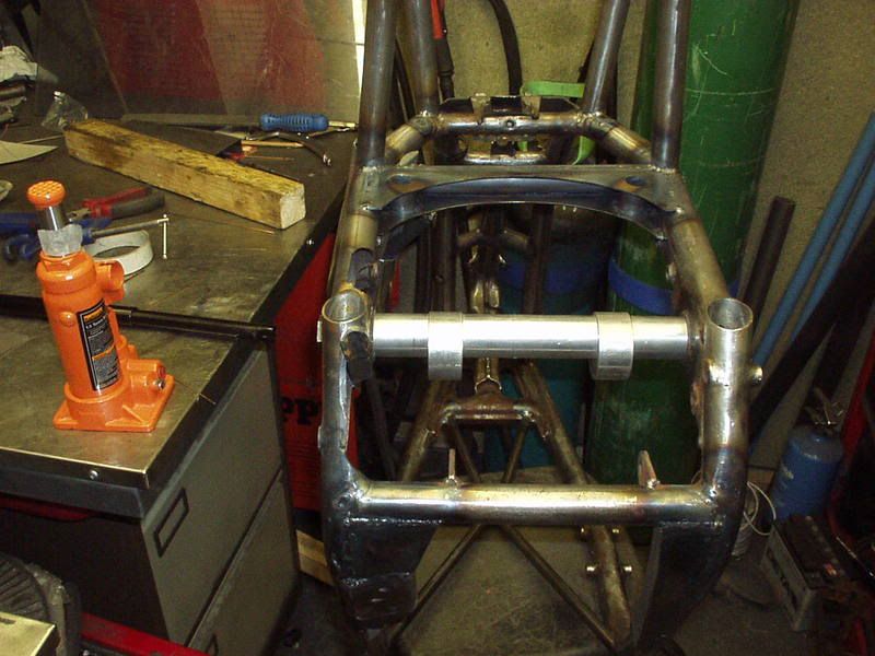 The tape on the jack is so I knew how much I had moved the pivot by (take up the slack & position the tape as a reference mark). Before leaving the jack in place whilst welding I had tried using the jack to give it a little stretch & then removing straight away but all that happened was it immediately sprang back as soon as the jack was removed. Appreciate I could have stretched it more but this is my frame The heat from welding made the difference in a non violent way No frames were killed in this process Although I'm sure the VJMC would disagree prob from page 1 of this project  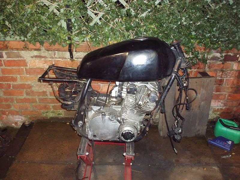 To finish this brace off I needed to form the curved section, here in place & not far off. 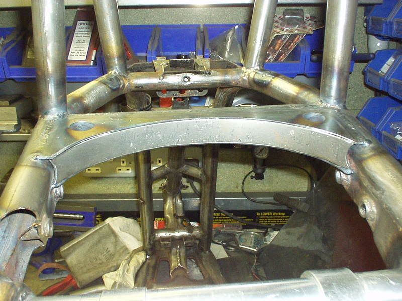 Weld a bit, grind a bit. 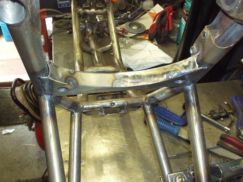 and then it was done I guess not be what your used to seeing & that's the point, I'm trying to make something which is a bit different. I love this, think it looks mad. Can't believe how long it took me though 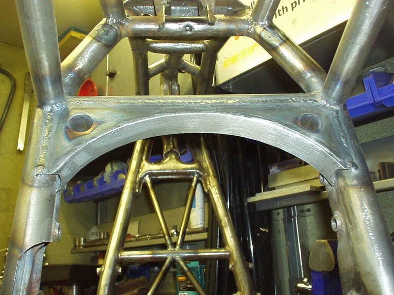 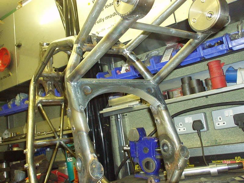 |
|
|
|
Post by captain chaos on Aug 9, 2013 17:16:53 GMT
Strangeland gets Stranger Today I hope to start working on a bit of stance, mounting the tank & side panels, few things to do first though. You might remember that I was dropping the petrol tank down at the front & raising the rear, already chopped off the mount for the tank rubbers & this is what was left. 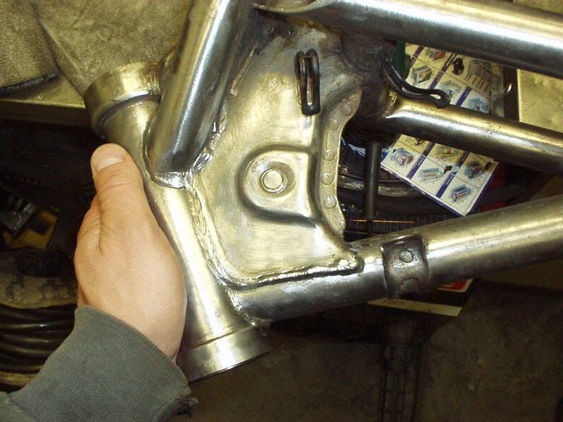 Found another use for the plasma 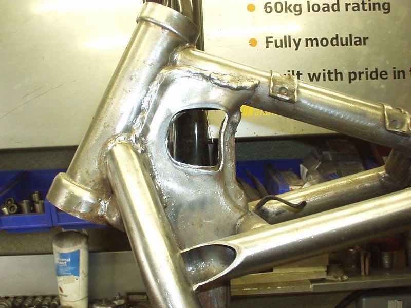 lookin good... what else needs doing after the panels are on? Whilst engine is in & I'm mounting the tank I'll sort out the coil mounts (Dynas). Up front I'm going to Yoshi spine it bracing wise but I do want to look see if I can't mod the main back tube to run wires thru. Rear subframe needs a cpl more tubes going in to triangulate it. Cross brace behind carbs. The area behind the side panels / under the seat will house the battery, Dyna 2000, reg rec, fuse block so mounts need for all that. The top sub frame tubes are cut off behind the top shock adjusters at a length 'longer' than I needed them to be, need to work into these the new tubes that will hold the tail section of the bodywork. Will be GS1000 but much modified. There were three main things in my mind when I was planning this bike in my head. 1) The method for moving the swingarm pivot & enlarging for the bigger spindle. 2) The top shock adjusters. These are both done & I think they rock. The 3rd thing is a bit of frame bracing which I think will make people double take it. It's not going to be overpowering but will be one of the stand out bits of the bike in terms of 'how the Fack did you do that'. If you thought doing the arch brace looked tricky you haven't see anything yet The top shock adjusters will be hidden behind side panels & people who haven't read this project won't know all the work that went into the swingarm pivot but this bracing will be visable. For sure will be one of the hardest things I've tried doing. I always removed the pressed steel crap when chopping GS frames... bit of additional bracing is just as strong and looks way better... just a thought mate. The only ugly bits on your frame are the Suzuki made bits great attention to detail, even on thing that will never be see... top work Arse, bollocks... wish I'd read that earlier as just spent a good few hours doing this to each side Cut metal filler plate to size. 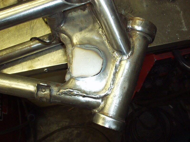 Weld & smooth. 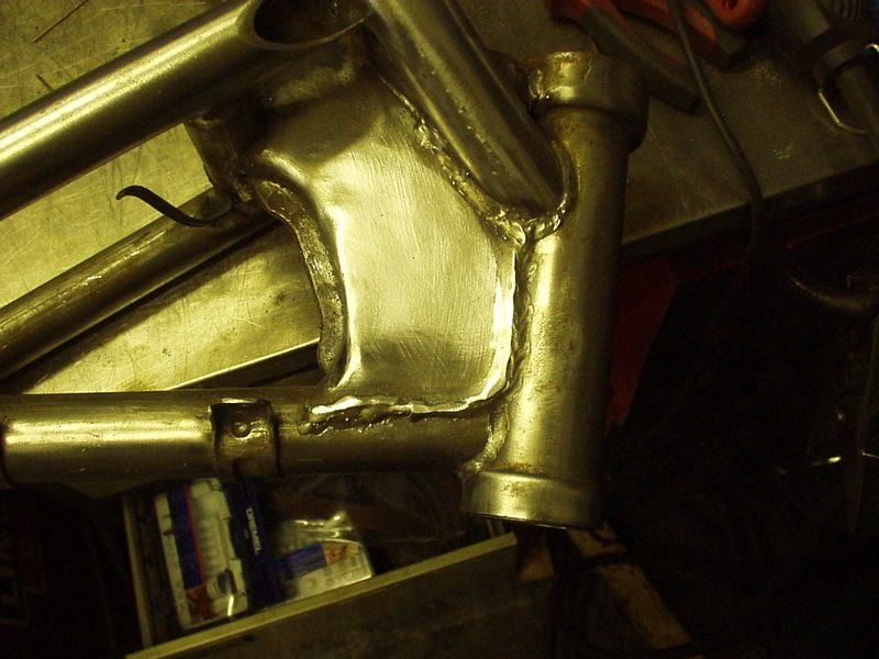 I'd prev measured off the flat plates & had Super Larry make me up 2 stubbs for the tank rubbers so maybe next time I do one of these I'll chop it all out. This is just a reminder of what was there but now I've got a totally flat surface to use, thought if I kept these it would look a right old bodge with my extra tank rubber stubs as well. |
|
|
|
Post by captain chaos on Aug 9, 2013 17:21:33 GMT
Struggled for time this week, spent a morning doing a few final welds on some of the tubes I'd put in, the hard to reach places that I had left till I had a few to do. Decided that I need to finish the chain cut outs before I do anything else & the first part of this is to weld in place the new footrest mount 'threaded sockets' that Super Larry had made for me. Drilled the new holes & started to grind down the one remaining original stub on this side, the other being on the lower subframe tube that has been cut off. I made a template of the other side (which are in a different location & that I will use) so I could mark the centers to match. 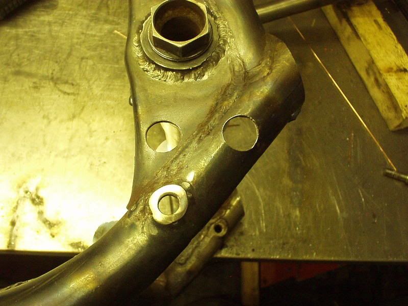 Got to cut & shut the footrest to work correctly how I want it but here I'm using it to hold the new mounts in place whilst I tac weld them. 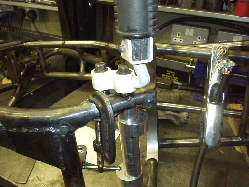 Fully welded & likewise the old mount removed & the hole welded up. 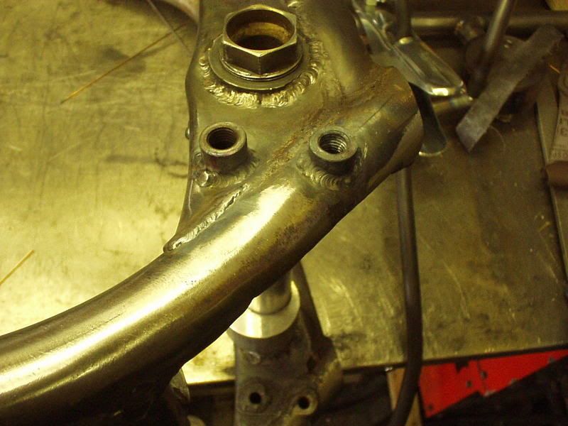 The back mount is lower as that's how it is on the other side. 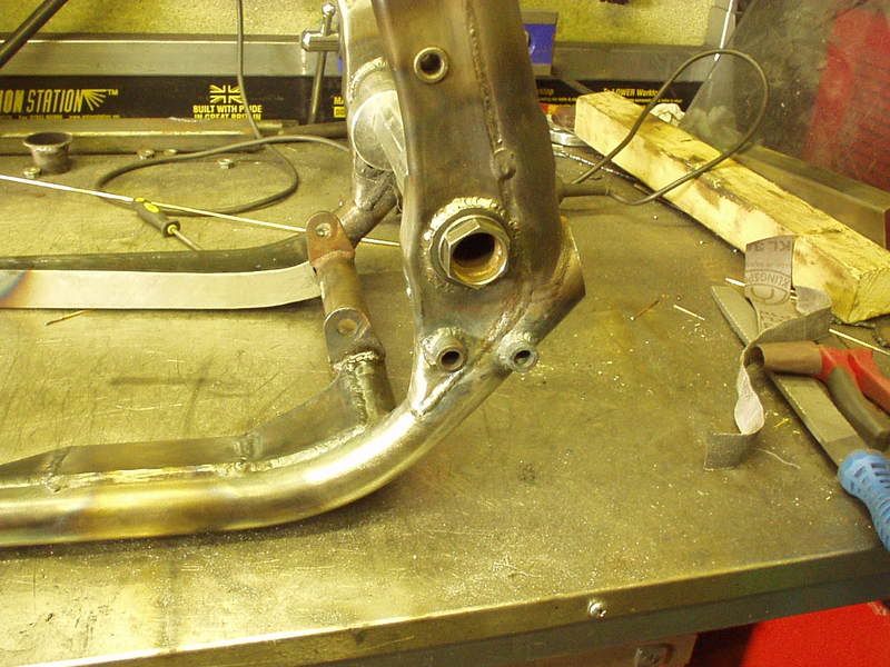 236 236
|
|
|
|
Post by captain chaos on Aug 9, 2013 20:08:16 GMT
If you like fabrication I think you'll like this Was in a more work less pics mode but got a few. You might have seen me do the chain cut outs before & know that I brace the tube inside before plating it back over. Thought of a better way of doing the bracing so that it resists movement in most directions. Not the best pic but you'll get the idea. Had some 16mm od tube & cut it into segments & went about placing the pieces of tube inside the frame & fully welding the sides of each segment. Built it up in layers, not sure what the tech term is but its almost like creating a honeycomb inside the tube (not finished in this pic).  Yes took bloody ages Here's the bottom cutout finished 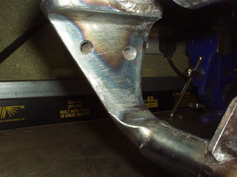 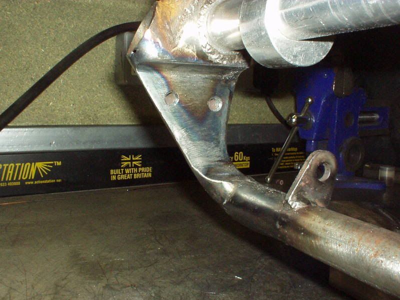 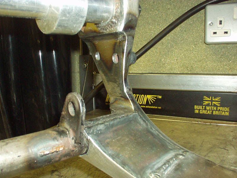 Need to do the same to the top cut out, if I have a good Sunday on it I might get that done & build it up back on its wheels & start looking at mounting tank & side panels. worked till 1am this morn but didn't quite get the top chain cut outs finished & couldn't get near the workshop today due to having to run around like an idiot. Took lots of pics, so here's a quick look at doing StrangeCuts This shows near the swingarm pivot the pieces of tube that form the edge/side of the cutout in place, the back part is angled due the swingarm sloping backwards from the pivot. Main purpose of this pic is to show the 2 infill pieces, one has had the weld filed smooth whilst the other shows a fat bead ready to file smooth (not a pretty weld but didn't need to be). 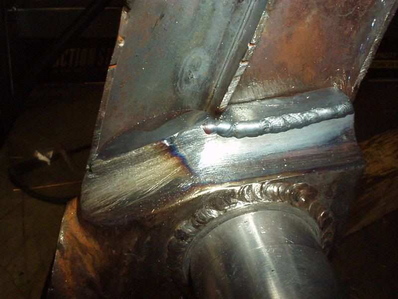 That done this next bit is important to the way I do these, I have put a small weld at the bottom of each infill piece, the infill is now joined top & bottom to the main frame tube. 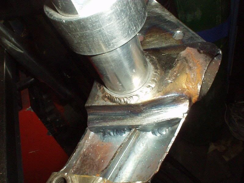 As I have moved the swingarm pivot upwards I decided to angle the top edge of the cut out as well, the engine mount fixes how high the front part of the cutout can be. 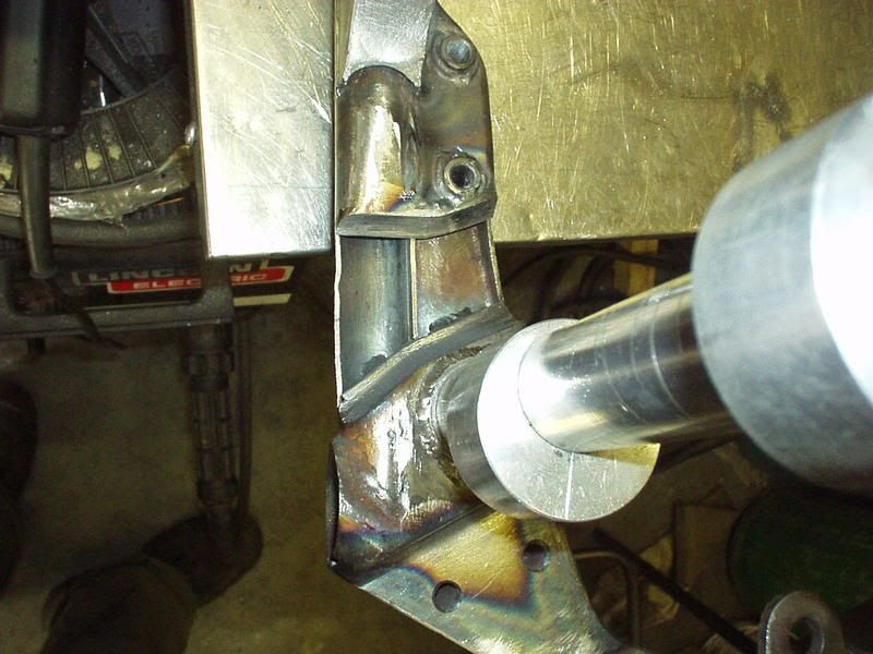 The tubed edges have been welded in place & files smooth. 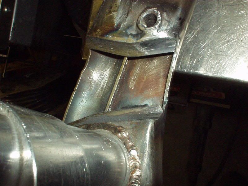 Next to do the 2 infill pieces for the top, I found that a 2 pence piece made a good template. 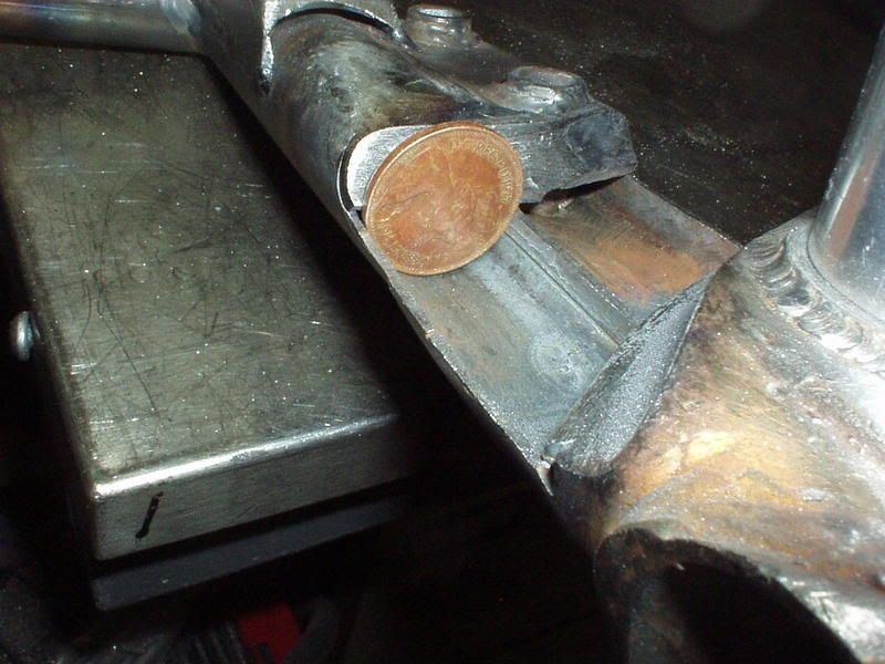 Made a template out of card & a good way of doing these (small bits) is to use a pair of mole grips to clamp the card template to a piece of metal & hold the mole grips in a vice. No burnt fingers & lots of access space to get in with the grinder. 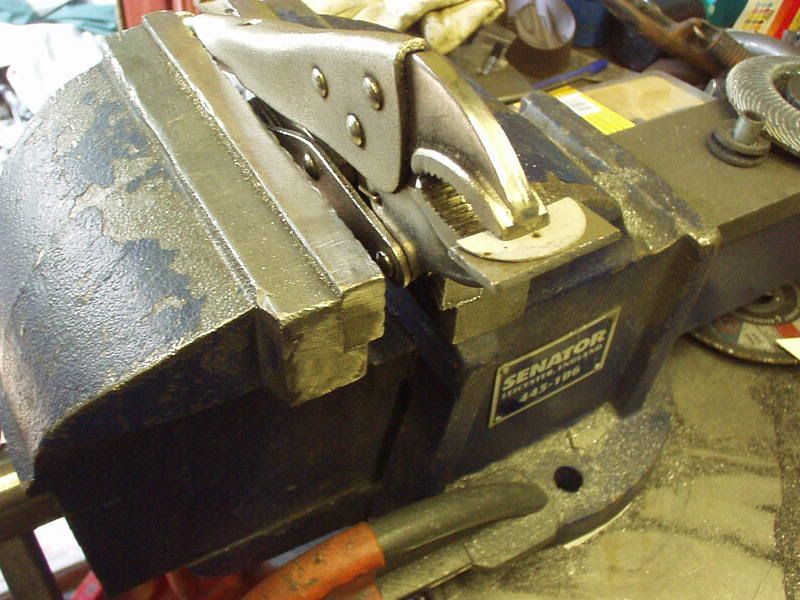 In place (scuse shite pic it was getting late :  . 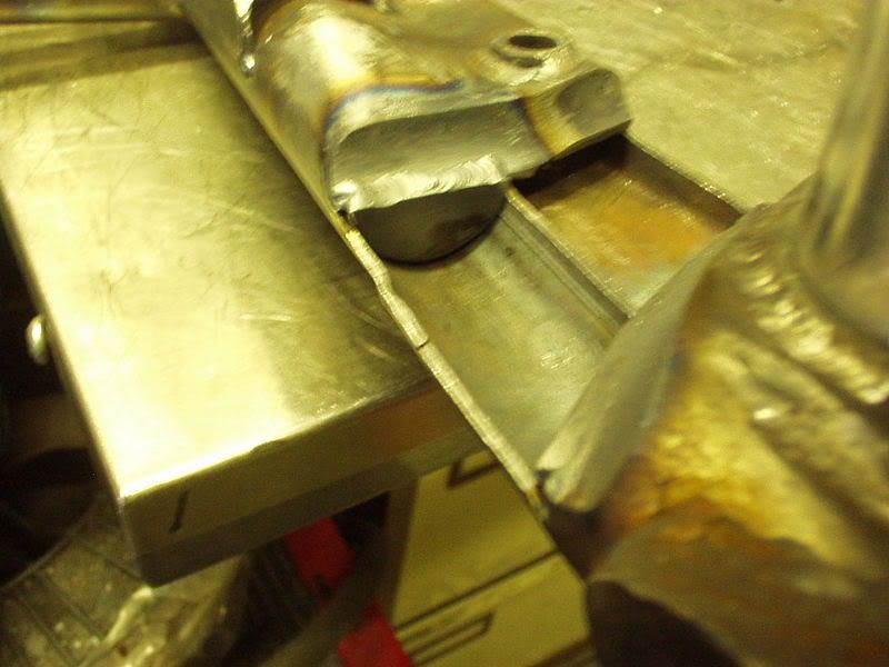 Clever bit next, I cut sections out of 16mm tube & laid them in place & fully welded all the sides. The not so clever part being unable to find (all) the pics I thought I had taken but here's one from which you'll get the idea. 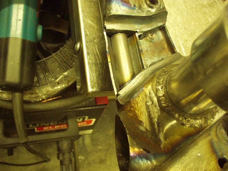 The sections of tubes are overlaid to form a honeycomb type structure inside the tube. No pics of this actual cutout but here is one from the lower chain cutout. That all done another cardboard template for the main side plate making sure it does fit in the space. 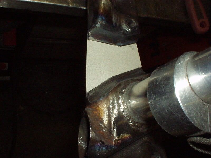 Combination of plasma & grinder & metal side plate in place. 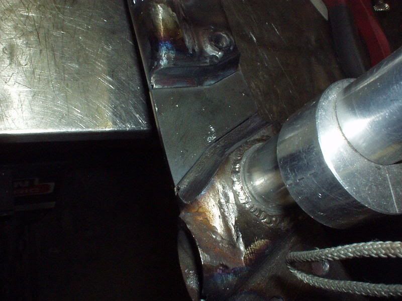 Thats almost where I am, have final welded & smoothed some of the plate edges but will finish that tomorrow. |
|
|
|
Post by captain chaos on Aug 9, 2013 20:09:29 GMT
|
|
|
|
Post by captain chaos on Aug 9, 2013 20:12:09 GMT
Lots of pics of it getting there, not all of bloody chain cut outs But seeing as they are finished here's what they look like. 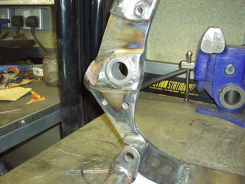 Rear. 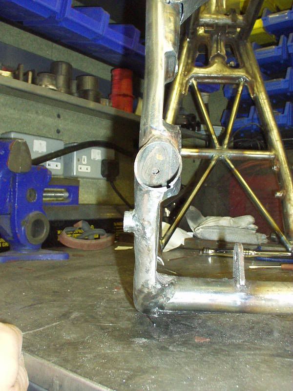 Front. 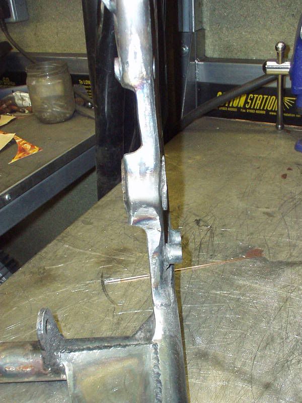 On its wheels, upper cut out . 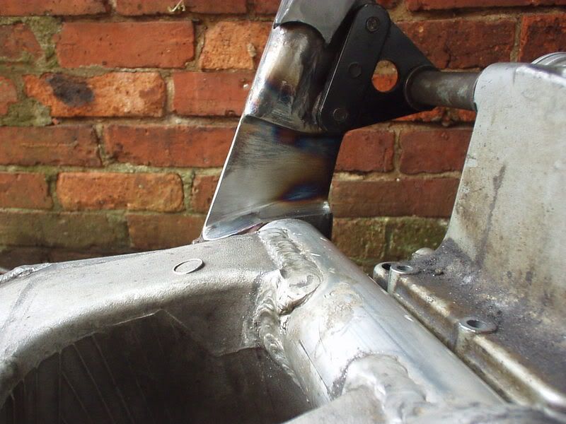 Lower. 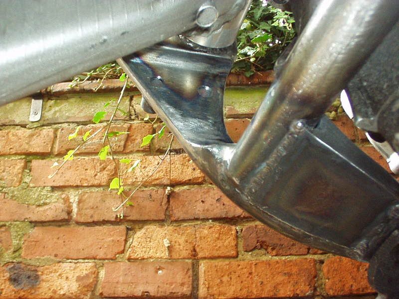 Clearance it all gives with a length of box held against the side of the 210 tyre. 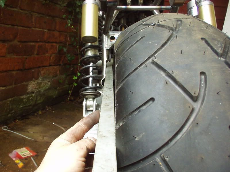 This pic shows how the bracing under the engine fits & the use of the existing sidestand mount as part of. 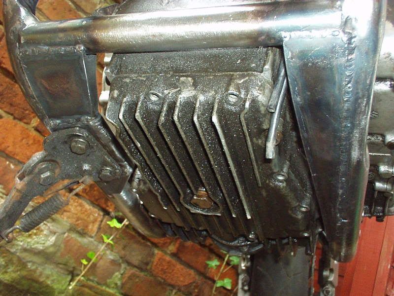 The GrebRod arch with engine mounts in place. 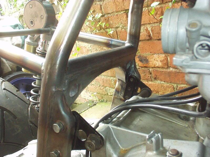 Gurgle. Lot of hours in that lot. 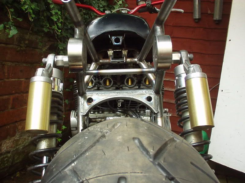 Side view without my lump on it. 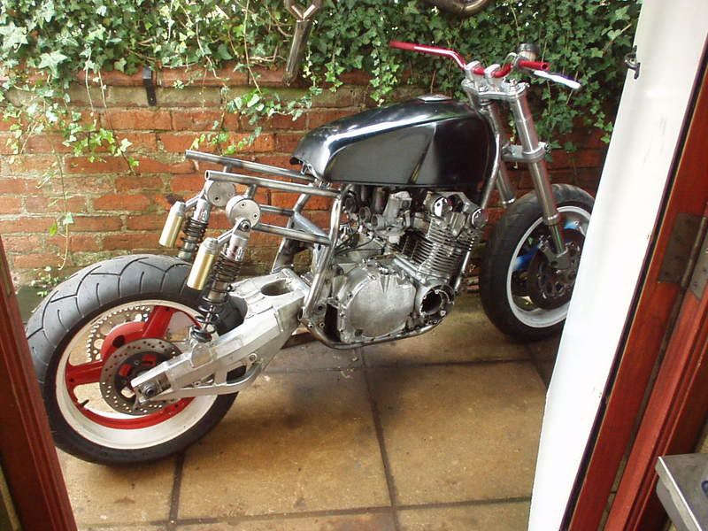 |
|
|
|
Post by captain chaos on Aug 9, 2013 20:14:35 GMT
Trying to think ahead what is going to hold me up which will be the engine top end going away for a bit of work So what I have made myself do is get the stuff out the way for which I need the engine, after which the engine can go on its travels whilst I finish the frame off. So, yes totally agree the subframe needs some triangulation but I don't need the engine to do that. Have put it back together as a roller so I can look at mounting 1) the side panels which I have to do before the tank so that they sit right with the top shock adjusters. 2) Having done that, the front top edge of the side panel will dictate where the petrol tank sits at the rear. Need the engine for this due to the closeness of the petrol outlet to the carbs. 3) Finding space for the dyna coils. Got distracted by doing the GrebRod arch as I didn't need the engine for that but thought it would be a 2 day job (Twit) & in doing that I found with the chain cutouts incomplete they were 'easily' distorted which was messing with the swingarm pivot frame bush on that side. Got everything back true & battled (it felt like it at times) through finishing the chain cut outs which brings us up todate. Which means. Reading Festival |
|
|
|
Post by captain chaos on Aug 9, 2013 20:16:56 GMT
Can't believe I woke up in the early hours concerned that Renthal's were prob a bolt on goodie persuaded myself they were more of a statement & fell asleep again Just need to get Reading Fest out my system.. Fack off you posh uni Twit & go steal someone elses stuff & burn someone elses tent & kit. Spent a few nights catching a cpl hours sleep with all valuables at the bottom of my sleeping bag, claw hammer in one hand & extendable baton in the other... whilst all the sheep ran around chanting 'angry mob'.. I ask you  Ok less bollocks more bike, side panels Unusually for me I though easy was best, got hold of some new rubber mounts for the tops of the panels. Each panel has a slot top front & rear which then hang over brackets on the frame. As I have made my own subframe needed to make some brackets. 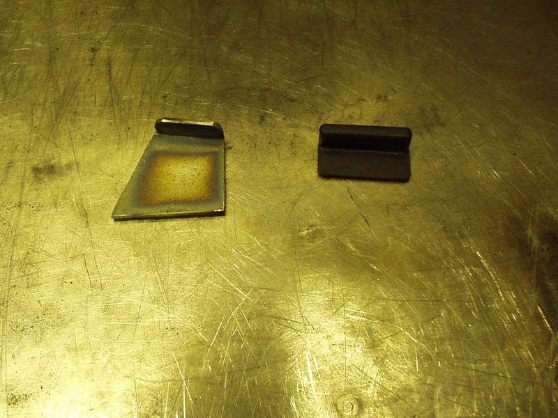 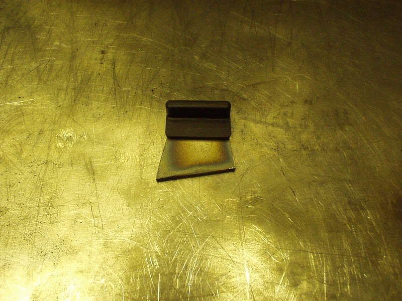 It was at this point I realised for the first time that the side panels are different lengths... I am going to cut & shut the rear tail piece because I want a different look for that but I want to keep the side panels mostly stock & for that reason I'm not going to modify the panels to make them the same. I'll put it down to the character of the original bike 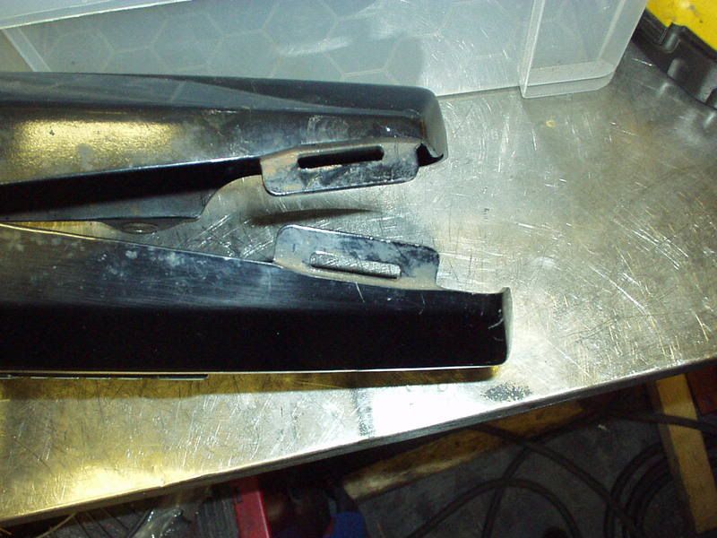 Very easy to forget how different the GrebRod is looking from stock, this is a pic of Froudster's GS (very nice). My thinking was that as intended the side panels aren't much of a feature, they get easily lost with everything behind them. The front part works with the shape of the airbox but the rear curve almost looks out of place with the lower subframe tube. 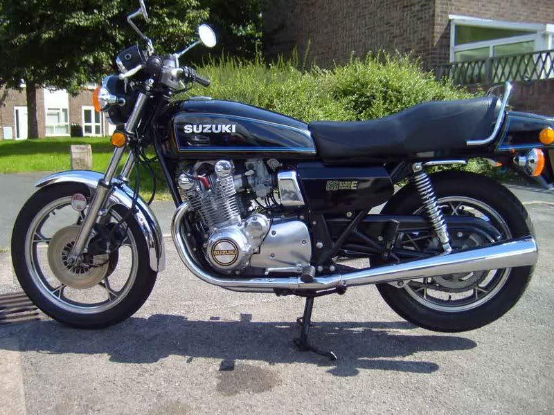 With GrebRod I've aligned the tops of the panels with the upper edge of the subframe tube, the rear curve is the same as the top shock adjusters & they are more noticeable due to the lack of much else around them. The front edge does not follow the line of the frame but cuts across it, this is a result of purposely angling the subframe for a more agressive look & I'm cool with that. Have a look at where Froudster's panel starts in relation to the rear engine mount bolts (above the swingarm pivot) & compare with the GrebRod, a lot higher due to the new subframe & raising the back of the tank (& dropping the front). 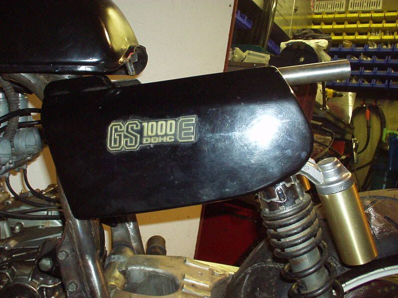 The shock mounts will be able to be seen as the lower edge of the tail piece will not sit below the level of the top subframe tubes. 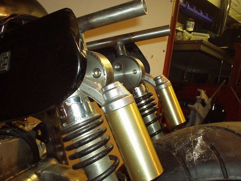 The design of the seat will play a big part in tying it all together styling wise. I'm loving how it's turning out, this next pic really shows how big the engine is looking with a lot of the stock stuff chopped off & thrown in the skip & the tank raised at the back to show the carbs off . 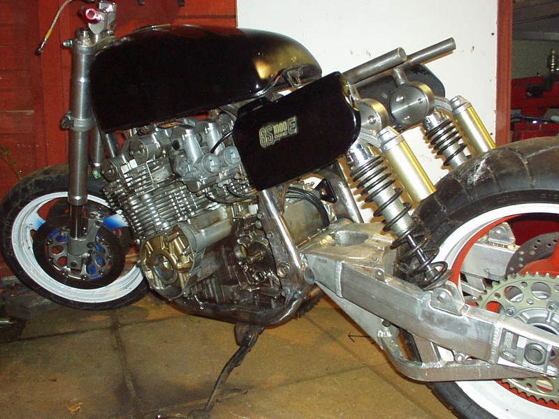 262 |
|


 .
.